maXim Operator Manual Appendix A
LSC Lighting Systems (Aust) Pty. Ltd. Page 62 of 66
to follow in numerical order. If a dimmer further along the line is to be also controlled by say
channel 13, then simply set its address switch to channel 13. The end of the DMX line is terminated
(120 Ω) to prevent the signal reflecting back up the line and causing possible errors.
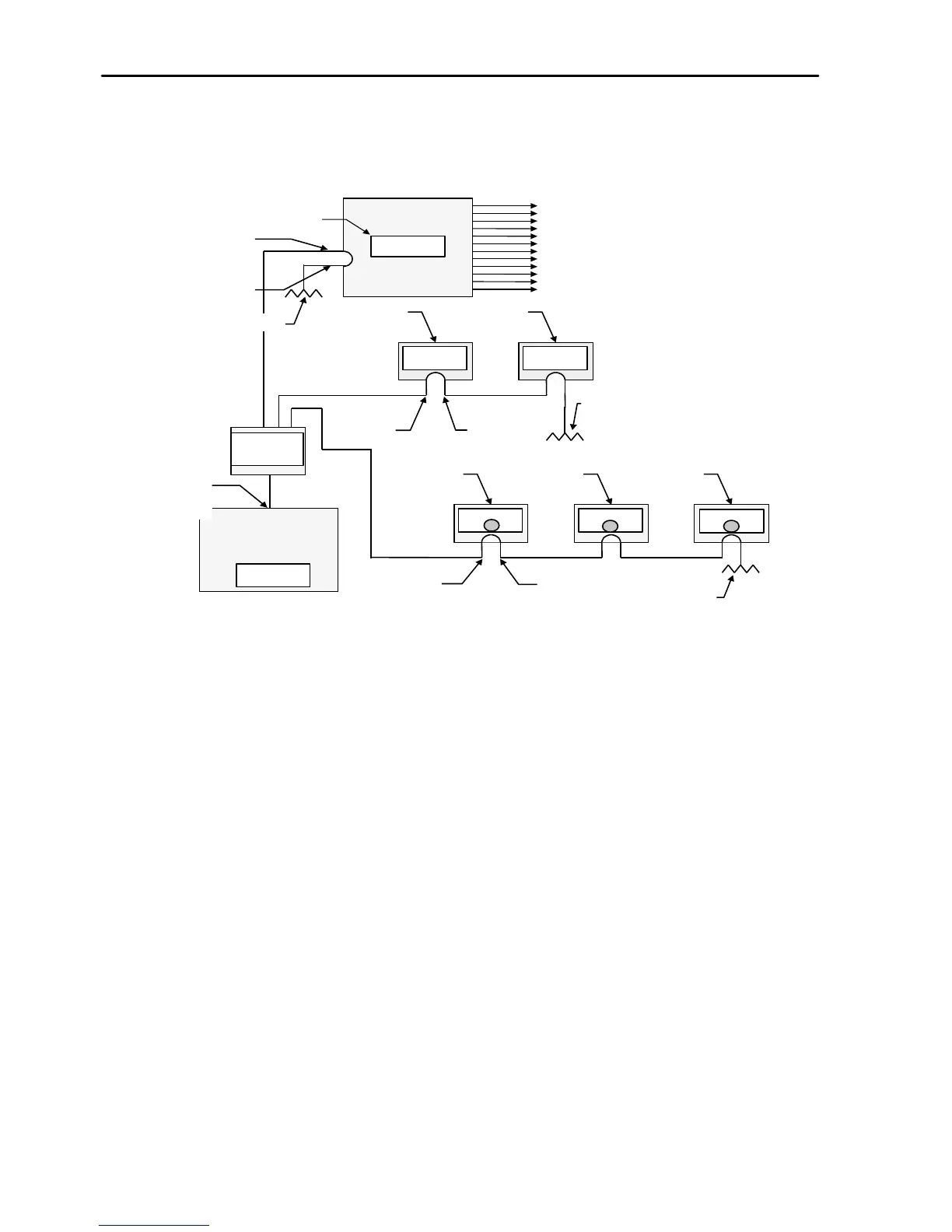
In this setup, the DMX is first fed to a splitter which isolates the input from the outputs. In the event
of a fault on one of the output loops, the other loops will not be affected. One output from the
splitter loops through dimmers, another loops through scrollers and the third feeds the De-mux.
Each device has its address set to read its own channel levels. The DEMUX box converts the DMX
signal into analogue signals to control analogue dimmers. As the DEMUX box is set to DMX
address 25, the 12 analogue dimmers would be controlled by channels 25 through 36. The end of
each DMX line must be terminated.