maXim Operator Manual Appendix A
LSC Lighting Systems (Aust) Pty. Ltd. Page 61 of 66
18.0 APPENDIX A: DMX 512
18.1 DMX512/1990
DMX512/1990 is the industry standard for the transmission of digital control signals between
lighting equipment. It utilises just a single pair of wires on which is transmitted the level information
for the control of up to 512 DMX channels. The information for each channel is sent sequentially.
The level of channel 1 is transmitted, then the level of channel 2, then 3, etc. up to a maXimum of
512 channels. This stream of data containing the levels for all 512 DMX channels is repeated a
minimum (generally) of 44 times per second. This provides sufficient updates of channel
information for smooth fade transitions.
When good quality data cables are used, DMX512 cable runs may be up to 1,000 metres in length.
Most DMX receiving equipment (dimmers, scrollers, moving lights, etc) are provided with a
DMX512 input and DMX512 output. This allows the DMX512 feed to be looped through various
pieces of equipment. DMX512 splitters may also be employed to provide multiple DMX512 feeds. If
a piece of DMX equipment regenerates the DMX signal, then the calculation of the 1,000 metre
cable length limit begins again from the output of the regenerating device
As the DMX512 signal contains the level information for all channels, each piece of equipment
needs to be able to read the level(s) of the channel(s) that apply only to that piece of equipment. To
enable this, each piece of DMX512 receiving equipment is fitted with an address switch. This switch
is set to the channel number to which the equipment is to respond. If the equipment is a rack of 12
dimmers, then the address switch is set to the channel number to which the first dimmer in the rack
is to respond. The other 11 dimmers will follow on from the channel number on the address switch
in numerical order.
18.2 DMX UNIVERSES
If more than 512 channels are required, then a second DMX output is provided.
The channel numbers on this second DMX output will also be 1 to 512.
To differentiate between the two feeds, each one is called a “Universe”.
• Universe 1 is channels 1 to 512.
• Universe 2 is channels 513 to 1024 (inside the maXim) even though its actual DMX
addresses are 1 to 512 on the universe 2 output.
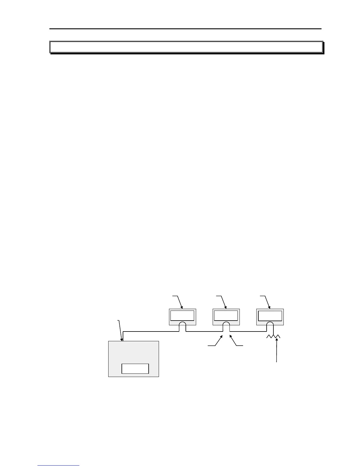
18.3 DMX512 APPLICATIONS
The following diagrams illustrate some simple setups utilising DMX512.
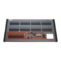
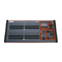
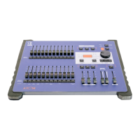
MaXim S
DMX 512
OUTPUT
In this setup, the DMX output signal from the maXim is fed to the DMX input of the first dimmer
rack. As the first dimmer in this rack is to be controlled by DMX channel 1, the address switch is set
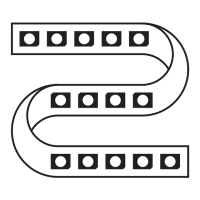
to channel 1. The DMX output connector of the first rack is connected to the DMX input of the
second dimmer rack whose address switch is set to 13 because the first dimmer in this rack is to be
controlled by channel 13. Further dimmer racks are connected in this daisy chain manner and their
addresses set accordingly. Address switches can be set to any desired address. They do not have