Chapter 8. Communication Driver
8-6
8.3.2 Connection Available Device
The range of the connection available device with the Dedicated Protocol used is as specified in 8.2.2 ‘ MASTER-K Loader
Protocol’.
Connection Available Area
Device
Bit Word Long
Remarks
D Area
D00000 –D4999F D0000 –D4999 D0000 –D4998
Ex.) D0000F :
D0’s bit 15
T Area
T0 –T255 T0 –T255 T0 –T254
-
C Area
C0 –C255 C0 –C255 C0 –C254
-
P Area
P000 –P63F P00 –P63 P00 –P62
-
M Area
M0000 –M191F M000 –M191 M000 –M190
-
L Area
L000 –L63F L000 –L063 L000 –L062
-
K Area
K000 –K31F K000 –K031
K000 –K030
-
F Area
F000 –F63F F000 –F063
F000 –F062
Read dedicated
S Area -
S00 –S99
S00 –S98
Bits Read
unavailable
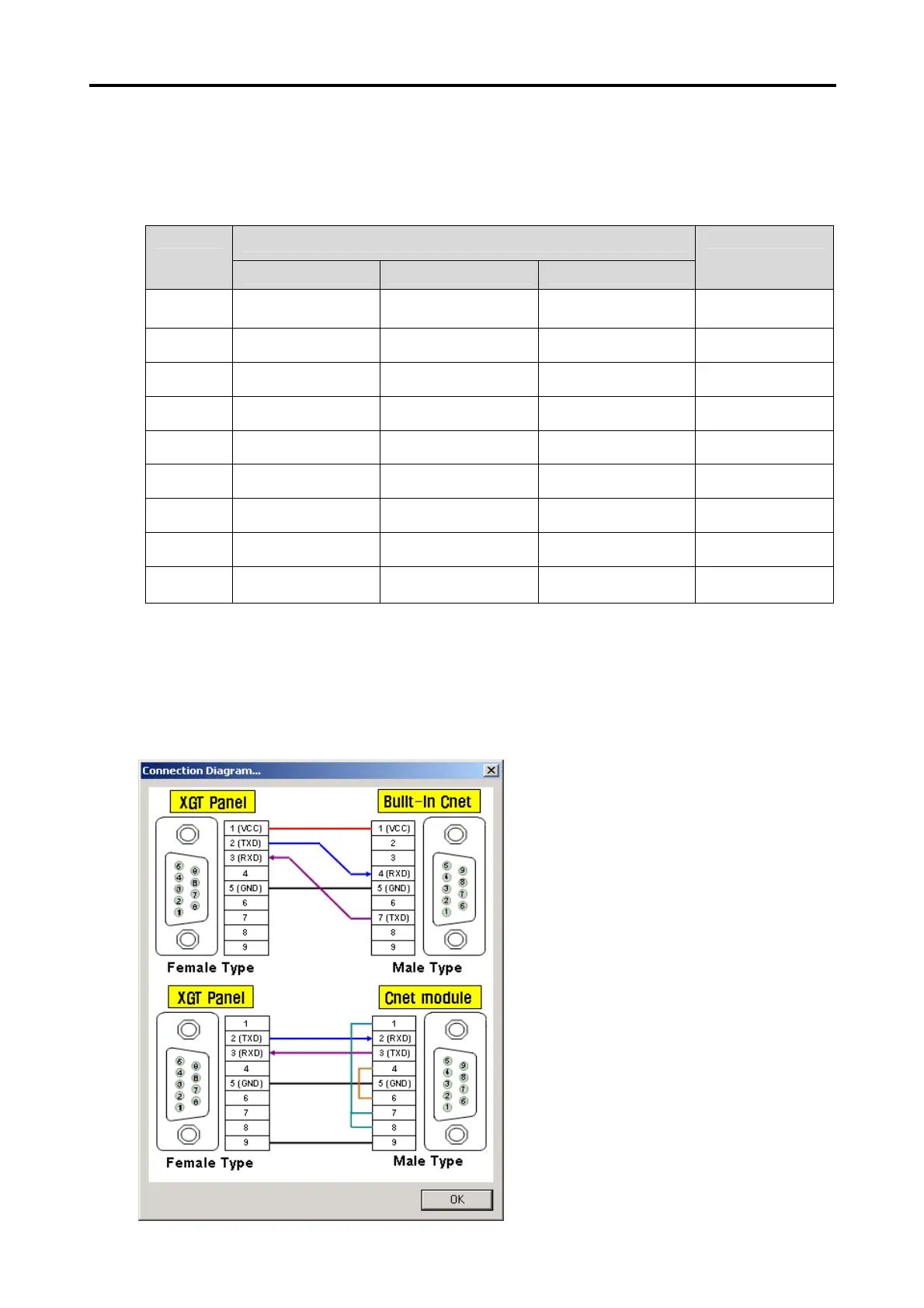
8.3.3 Connection Diagram
If the Dedicated Protocol is used, the Connection Diagram of XGT Panel and MASTER-K series is as shown below.
Use the Connection Diagram button of PLC Type Change on the Panel Editor to check the Connection Diagram below.
1) CH 1(if connected with RS-232C used)