Chapter 8. Communication Driver
8-11
8.5.3 Connection Diagram
The Connection Diagram of XGT Panel and MASTER-K10/30/60/100S is as shown below..
Use the Connection Diagram button of PLC Type Change on the Panel Editor to check the Connection Diagram below.
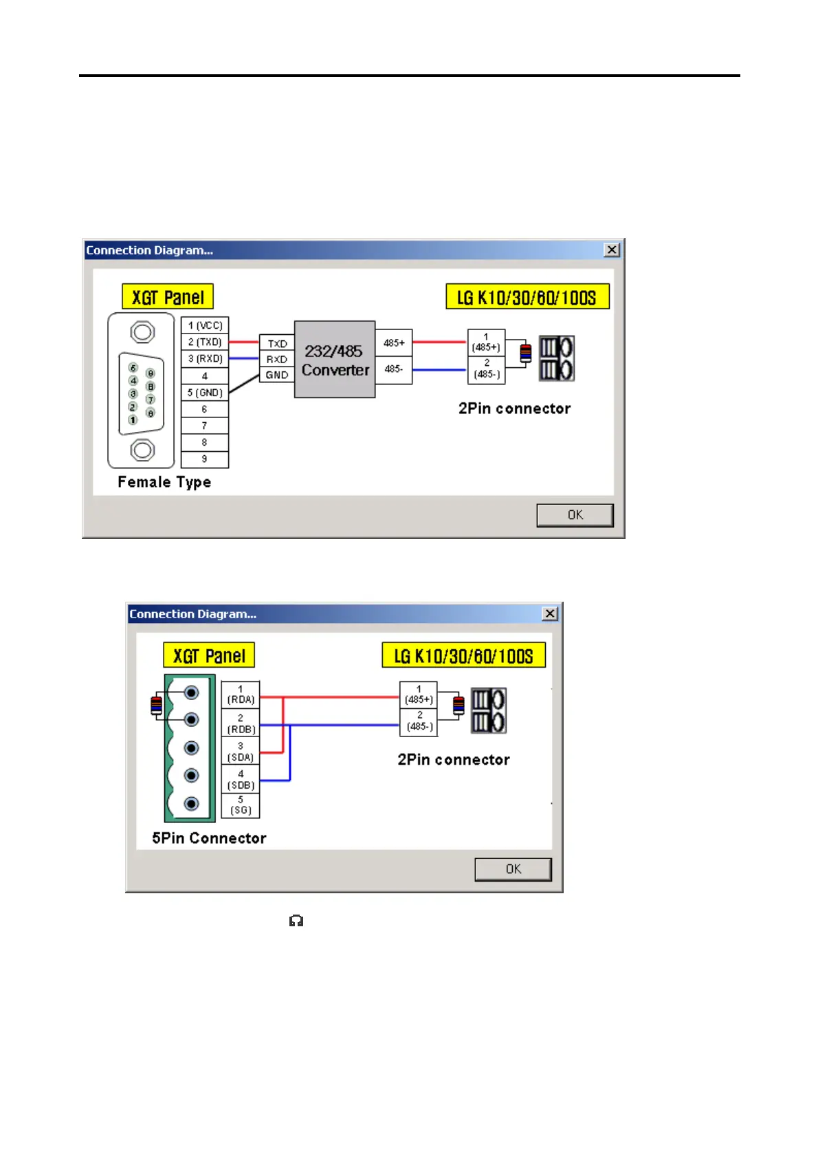
1) CH 1(if connected with RS-232C used)
2) CH 2(if connected with RS-422/485 used)
* Use terminal resistor 120