Appendix
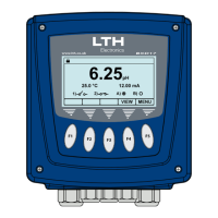
BPD17 pH / Redox Monitor
Operating Guide
- 69 -
The Sensor Reading Is Incorrect
Check that no error messages are being displayed. Check that the sensor cable has been correctly
connected (see Installation Section, Page 20).
Check that the Temperature reading is correct.
Check the instrument calibration using a pH simulator, Adjust the channel calibration if necessary
(see Calibration Section).
Use another instrument to check the sensor.
The Sensor Is Not Functioning Correctly
Check that the sensor glass is not broken or cracked.
Check the reference probe KCl (where applicable) for leakage or contamination.
Ensure all probe protective caps have been removed.
Check that any junction boxes used are correctly connected.
Check that a suitable high impedance, low noise cable has been used.
Check for damaged or broken cables.
Check for damp, grease, or liquids near connectors, junction boxes, or terminations.
Where extension cables have been used, try connecting the sensor directly to the instrument.
The Temperature Reading Is Incorrect
Check that the temperature sensor is correctly attached. (Installation Section, page 25).
Check that the temperature sensor type is correctly selected in the Channel Setup menu (See page
30)
Where practical check the temperature sensor resistance against the table on page 65.
Current Output is Incorrect or Noisy
Check that the maximum load for the current loop has not been exceeded. (750).
Check that the terminals have been wired correctly.
Check that the cable screen is attached to Earth at one end and that the cable does not pass too
close to a power cable.
Check that he current output has been configured properly.
Relays Appear to Malfunction
Check that the unit is “On-Line” (Page 27)
Check that the set point has been configured properly.
If the relays are vibrating or “chattering” as they pass the set point, check the hysteresis setting and
increase if necessary.
Ensure that the relays are connected properly and that the voltage/current levels are not exceeding
5A @ 30V DC or 5A @ 250V AC.
Check that the instrument input cables are not picking up excessive noise.
Problems with Cables and Connectors
The cable connecting the pH probe to the instrument is the most common cause of problems in pH
measurement systems. The importance of the following recommendations cannot be over stressed.
Input Resistance
The high input resistance, required for the optimum performance from a pH electrode system, will be
seriously degraded if any grease, dirt, or dampness is allowed to collect around any of the connections
between the probe and the instrument. This includes any connectors or junction boxes which may be
used. Particular attention must be paid to the method of extending the pH electrode cable. A general
rule would be the fewer connections there are, the less problems are likely to occur.