A-2 Issue 4 February 1997
363-208-011
Applications
Peripheral Equipment
Interconnections
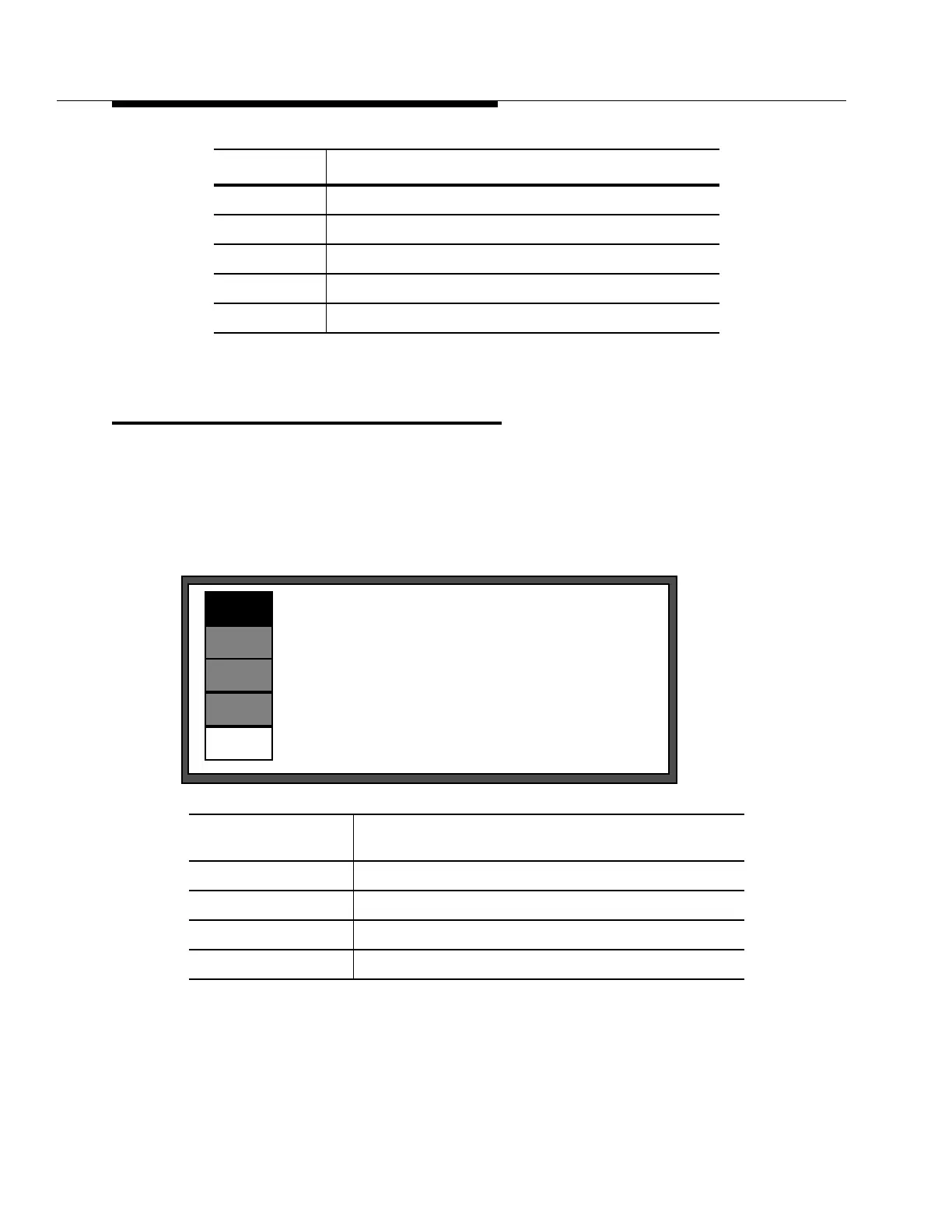
Figure A-1 represents the major peripheral equipment connections from the
SLC
-
2000 COT as well as all inter-shelf installation cables. Refer also to Figure A-9 for
detailed PGTC/
SLC
interconnections; Figure A-10 for Synchronization interfaces,
and Figure A-11 for OS interfaces. Cable assemblies are represented by the
following legend:
Figure A-7 COT Alarms
Figure A-8 Power and Ringing Interconnect
Figure A-9 PGTC and DC Access Test Pairs
Figure A-10 Network Synchronization Interconnections
Figure A-11 Operations Systems Interfaces
Bay cable assemblies Local inter-shelf cables shipped separately with the COT
bay equipment but not associated with a particular shelf.
Standard shelf dangler Cables shipped as part of the associated shelf.
Optional shelf dangler Cables shipped with the shelf for a particular application.
Backplane connection Associated shelf connectors for cable connections.
Customer interfaces Cable assemblies for connecting peripheral equipment
Figures Description
Bay Cable Assemblies
Standard Shelf Dangler Cables
Optional Shelf Dangler Cables
Customer/Peripheral Equipment Interfaces
Backplane or Intrashelf Connections