363-208-011
Cabling, Wiring, and Assembly
Issue 4 February 1997 3-47
Connections
Step 1:
Install the VF Interface Cable Assemblies in the appropriate duct and
mate their connectors with the connectors of the MDS shelf in accor-
dance with the associated figures in the tables below:
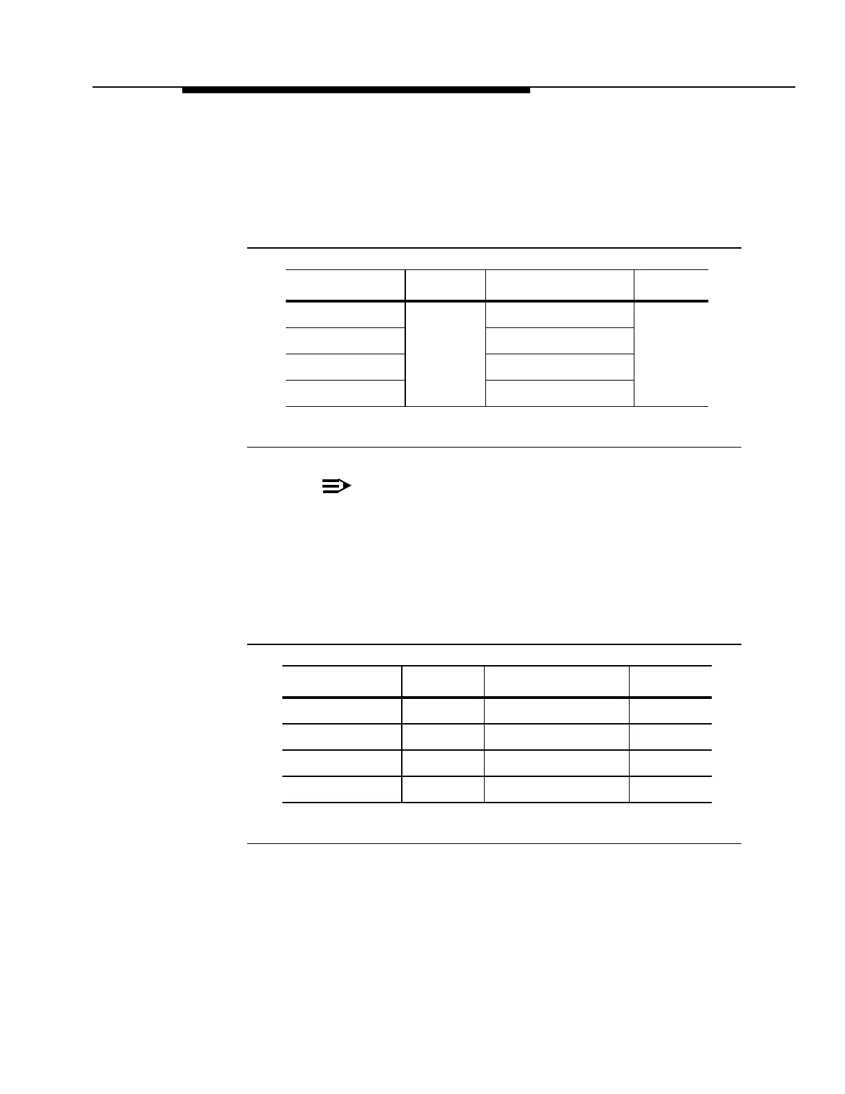
Table 3-2. VF Connections
NOTE:
Stamp each connector (J101 to J204) before mating to its
associated connector.
Step 2:
Terminate the VF pairs at the MDF and label the cables, connectors, and
the conductors in accordance with the figures for the J101 to J104 and
J201 to J204 connectors. Note the wire color coding sequence of the
factory prepared cable assemblies to facilitate the terminations.
Table 3-3. VF Channel Number Identification
Step 3:
Orient the mating cable connectors so that the customer cables exit
upwards towards the cable racks. Refer to Figures 3-30 and 3-36.
Left Cable Duct Figure Right Cable Duct Figure
J201 to P201 3-35
and
3-36
J101 to P101 3-29
and
3-30
and
3-34
J202 to P202 J102 to P102
J203 to P203 J103 to P103
J204 to P204 J104 to P104
Left Cable Duct Figure Right Cable Duct Figure
J201 3-37 J101 3-31
J202 3-38 J102 3-32
J203 3-39 J103 3-33
J204 3-40 J104 3-35