2-10 Issue 4 February 1997
363-208-011
Installation Procedures
Step 3:
Each equipment shelf is equipped with a ground wire which must be
bonded to the bay framework. Refer to the section Mounting System
Shelves for details.
Step 4:
The ARM shelf has also one ESD ground wire which must be bonded to
the bay framework. Refer to the section Mounting System Shelves for
details.
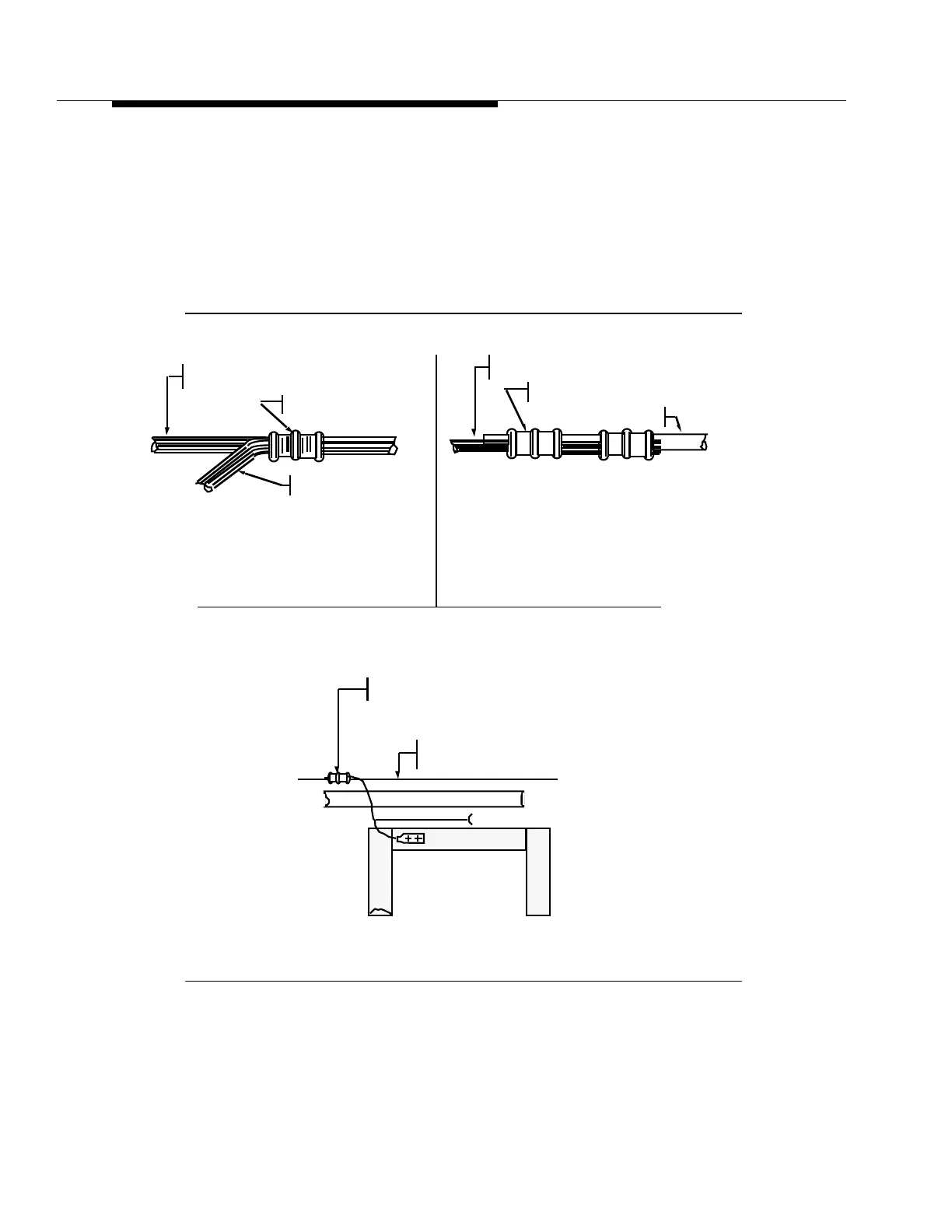
Figure 2-4. Grounding Connections
Stranded To Solid Copper Wire
Crimp Connector Assembly
For
No. 2 Or No. 6 AWG
Figure B
54740 Compression C Tap
(Thomas & Betts) 2 Required
No. 6 AWG
Stranded Wire
No. 2 AWG Solid
Ring Ground
Stranded To Stranded Wire
Crimp Connector Assembly
For
No. 2 Or No. 6 AWG
54720 Compression C Tap (997775952)
(Thomas & Betts)
Figure A
No. 2 AWG Stranded
Ring Ground Wire
No. 6 AWG Stranded
Ring Ground Wire
NOTE 1:
The “C” Type Tap Shall Always Turn
In The Direction Of The Closest
Ring Bus Bond.
Join 54720 (Thomas & Betts)
Compression "C" Tap To Ring Ground Wire
See Note 1 And Figure A And/or Figure B
No. 2 AWG
Stranded Wire
Ring Ground
Bay Framework Rear View)
Provided With Bay Frame
Figure C
Part Of Cable Rack