3-2 Issue 4 February 1997
363-208-011
Cabling, Wiring, and Assembly
f. Discrete alarm connections for environment status and controls.
g. Power connections from the -48 volt battery plant.
h. Ringing connections from the customer’s positive and/or negative ringing
supplies.
i. Synchronization inputs from the office clocks supplies.
j. Operational System (OS) inputs from remote maintenance centers.
These external cables must be engineered for the complete installation of the
SLC
-2000 COT Frame.
NOTE:
All cables are not required for each installation. See Notes 201 and 202 on
Sheet D1 of SD7C180-01 for information about the orderable customer
interface cables for central office applications. Refer to the engineering
specifications for a particular office application.
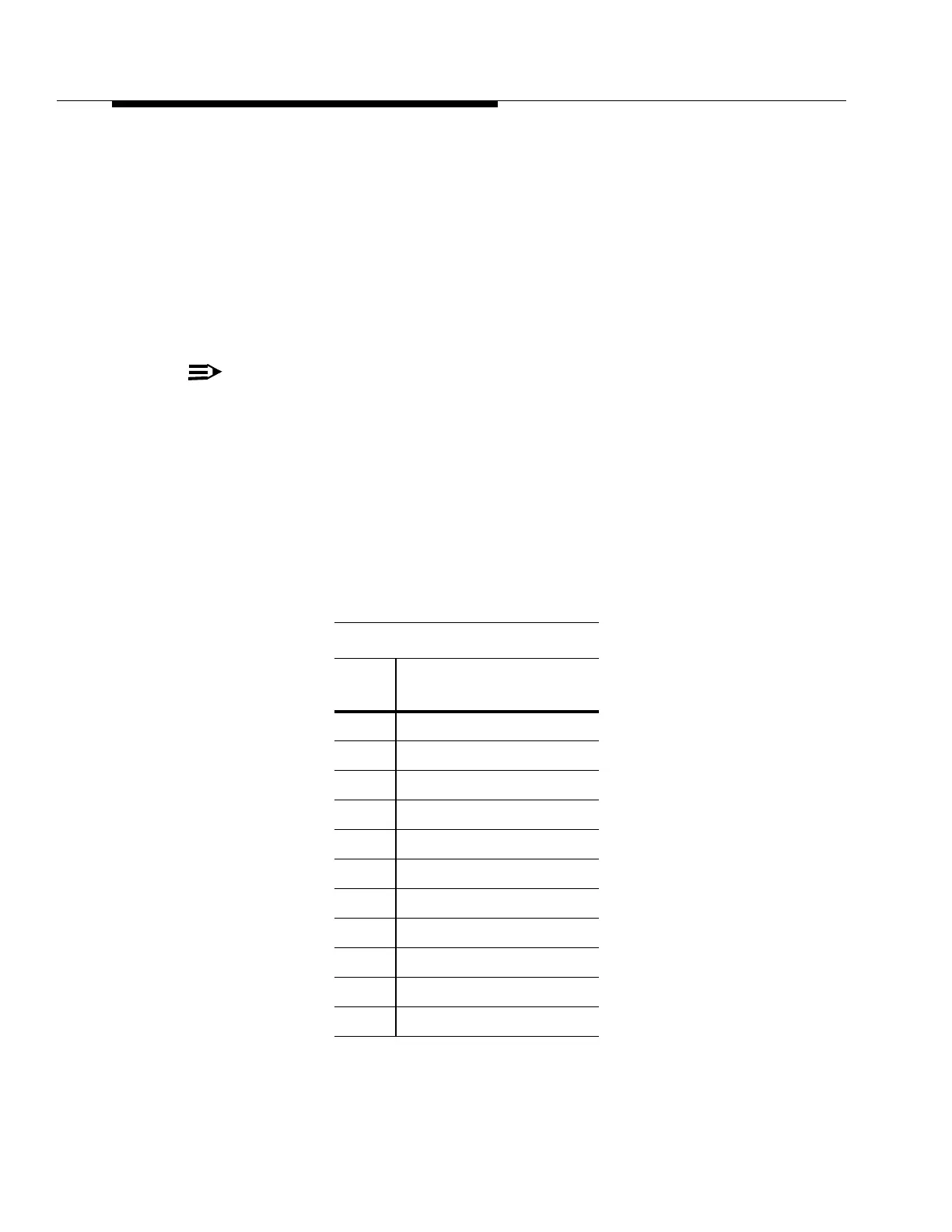
Factory Cable Assembly Wire Color Coding Sequence
Standard wire color coding for the factory assembled cables is shown in the
following table. This coding sequence is followed on VF, DS1 and other cables
used as danglers and as Customer Interface connections. Use of the color coding
will facilitate both terminating operations at the customer’s cross-connecting
points and troubleshooting routines.
Conductor Identification
Pair
No.
Colors
(Tip/Ring)
1 white-blue/blue-white
2 white-orange/orange-white
3 white-green/green-white
4 white-brown/brown-white
5 white-slate/slate-white
6 red-blue/blue-red
7 red-orange/orange-red
8 red-green/green-red
9 red-brown/brown-red
10 red-slate/slate-red
11 black-blue/blue-black