LT10A / LT11A Series
14 (E)
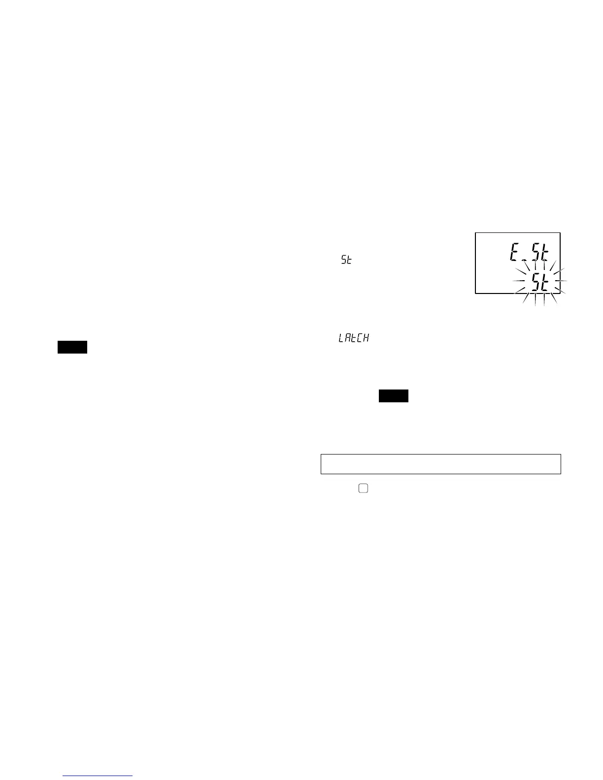
4. Selecting the start input terminal (I/O connector)
function
(See “6. I/O connector”.)
:
Start function
Setting this terminal
to “L” (ON) sets the
peak-hold value to
the current value and
restarts the storing
procedure.
: Latch function
When using the current value measuring
mode, setting this terminal to “L” (ON) stores
the output and display of the Go/No Go
comparison at that point in time.
Note
When the latch is ON, display and Go/No Go
output storage by the DRQ input for the BCD
model and RS-TRG input for the RS-232C
model is invalidated.
Initial settings are now complete for the standard model.
Pressing
.. Standard model → Returns to the measuring
state.
BCD model → Go to section 5-1-2.
RS-232C model → Go to section 5-1-3.
3. Setting the display resolution or direction
(channel B, 2 channel models)
0.001/0.005/0.01/–0.001/–0.005/–0.01 mm.
• With the measuring unit’s spindle pushed in:
+: positive direction
–: negative direction
• When displaying A+B:
If you set the direction of A to “–” the data displayed is
the calculation “–A+B”.
The same can be done with B.
Note
• With the LT10A series, 0.001 mm and –0.001 mm
(0.0001" and –0.0001") are not avaible.
• When the addition A+B is chosen the direction for B can
be selected, but its resolution will be the same as that of
A.
factory-set