LT10A / LT11A Series
16 (E)
: Outputting with measuring mode information
and comparator Go/No Go result
1st byte : Channel name (A or B)
2nd byte : Current mode
(N: Current value,
P: Peak-to-peak value,
I : Minimum value,
A: Maximum value)
3rd byte : Unit (M: mm, I: inch)
4th byte : Comparator Go/No Go
result
U : Upper limit over
G : Within range
L : Lower limit under
E : When an alarm has
occurred
5th byte : Sign (“+”
or “–”)
6th to 11th bytes
: Numerical data
(ex.00.000)
: Outputting according to the mode 1 format
(statistical calculations) of the digital
printer P40 (End of sales).
Whether, with the 2 channel model, to
output B channel data following a
space or to divide it with the
delimiter is selected by step 9.
(except for P40 mode)
Note
When set to mode even the
2 channel model only outputs the A
channel.
: (“+” or space)
factory-set
5-1-3. RS-232C model
(only LT10A-105C/205C, LT11A-101C/
201C)
Proceeds to the next setting mode from “5-1-1. Basic
settings” step 2.
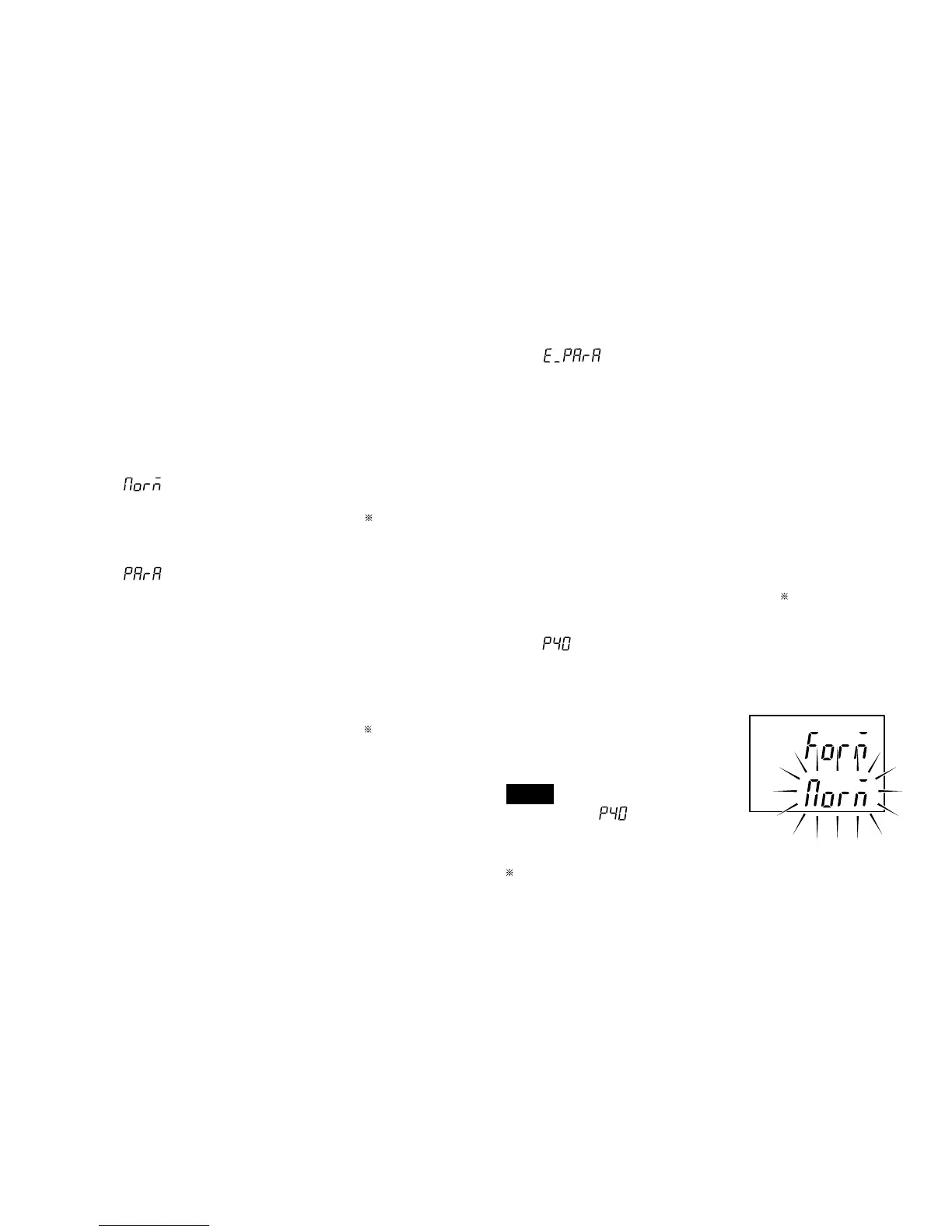
1. Setting the output data format
: Normal output
1st byte : Channel name (A or B)
2nd byte : Sign (“+”
or “–”)
3rd to 8th bytes: Numerical data
(ex.12.345)
: Outputting with measurement mode
information
1st byte : Channel name (A or B)
2nd byte : Current mode
(N: Current value,
P: Peak-to-peak value,
I : Minimum value,
A: Maximum value)
3rd byte : Unit (M: mm, I: inch)
4th byte : Sign (“+”
or “–”)
5th to 10th bytes
: Numerical data
(ex.00.000)