LT10A / LT11A Series
24 (E)
Start/latch input
• The “L” (ON) signal sets the maximum, minimum, and
peak-to-peak values to the current value and restarts
their storing. (Start function)
• If, when the initial setting of
which was set at the time
of shipping is changed to
, the current value mode
serves as the measuring mode, the “L” (ON) signal will
hold the Go/No Go output (I/O connector) and display.
(Latch function)
Note
While the Go/No Go output is at the “L” level, reset/preset
value recall cannot be effected by reset key or external
reset/preset value recall input.
Reset input
“L” (ON) sets the measured value to zero.
When there is a preset value this is recalled.
Note
Even when the “L” level is held, the Go/No Go output (I/O
connector) and the display are not held.
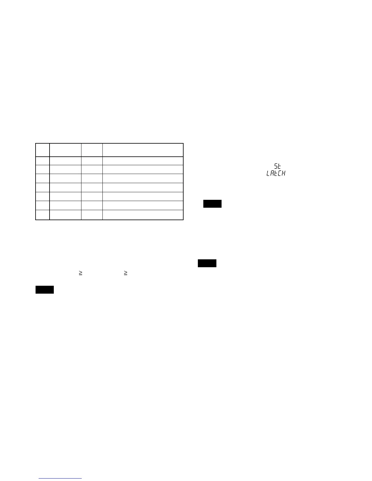
I/O connector (common)
Pin Signal
IN/OUT Signal
No. name
1 GND –
2 START (A) IN Start/latch input (A)
3 PAUSE (A) IN Pause input (A)
4 START (B) IN Start/latch input (B)
∗
1
5 PAUSE (B) IN Pause input (B)
∗
1
6 RS-TRG IN
RS-232C data output/trigger input
∗
2
7 GND –
✽
1 : The connection of this pin is prohibited for 1-channel
models.
✽
2 : The connection of this pin is prohibited except in RS-
232C models.
Go/No Go output
High: displayed value > upper limit → “L” (ON)
Go : upper limit
displayed value lower limit → “L” (ON)
Low : lower limit > displayed value → “L” (ON)
Note
All Go/No Go outputs are “H” (OFF) when an alarm is set.