LT10A / LT11A Series
28 (E)
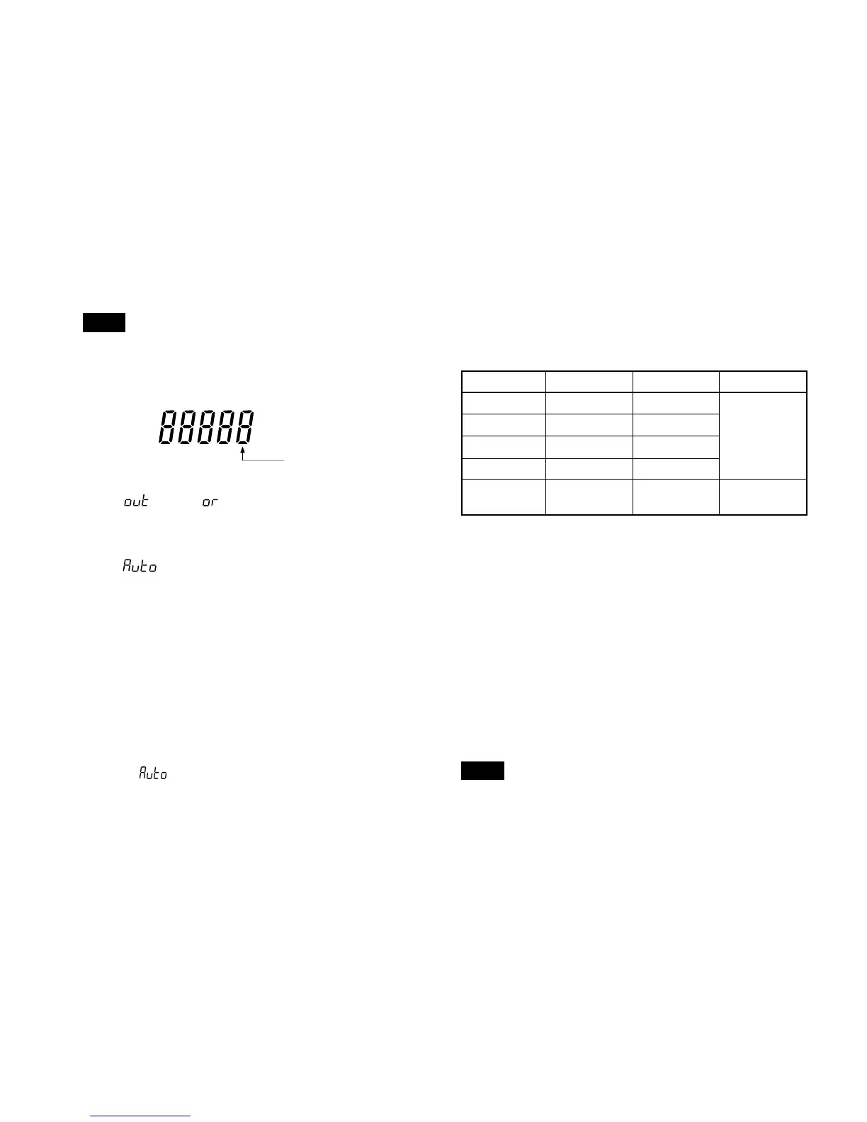
1st digit
Note
• The counter unit’s least significant digit (rightmost digit) is
the first digit.
The letters in parentheses have the following meanings
A: 1, B: 2, C: 4, D: 8.
BCD output
In the
mode, mode
(See “7-2. I/O timing”.)
When DRQ has been received from at #0, and when the
READY output at #1 goes “L” (ON), the BCD data is output.
In the
mode
The data is output at the output time interval which was set
as the initial setting even when DRQ is not input.
• Output logic
True logic or false logic can be selected.
(See “5-1-2. BCD model”)
True logic : “L” (ON) is “0”.
“H” (OFF) is “1”.
• Output format
Whether to hold the BCD output data or to assume
high-impedance when there is no DRQ signal input can
be selected.
(See “5-1-2. BCD model”)
In the
mode, the unit cannot enter the high-
impedance state.
Measuring mode selection input
Current value, maximum value, mimimum value, peak-to
peak value can be selected.
×: Either setting possible
SIGN output
Tells whether the output data is positive or negative.
With true logic “H” (OFF) is “–”, and “L” (ON) is “+”.
Start input
When the peak-hold function has been chosen the “L” (ON)
input will cause the maximum value and minimum value, to
be come the current value (peak-to-peak value = 0) and
restart their storing.
Reset input
“L” (ON) sets the measured value to zero.
When there is a preset value this is recalled.
Note
Even when the “L” level is held, the Go/No Go output
(terminals) and the display are not held.
Measuring mode
Current value
Maximum value
Minimum value
P-P values
According to the
key switch settings
@
1pin (MOD 0)
L
H
L
H
✕
@2pin (MOD 1)
L
L
H
H
✕
@
3pin (M-VALID)
L
H