5
7
8
9
Check the base fitting of the high−pressure pump
25
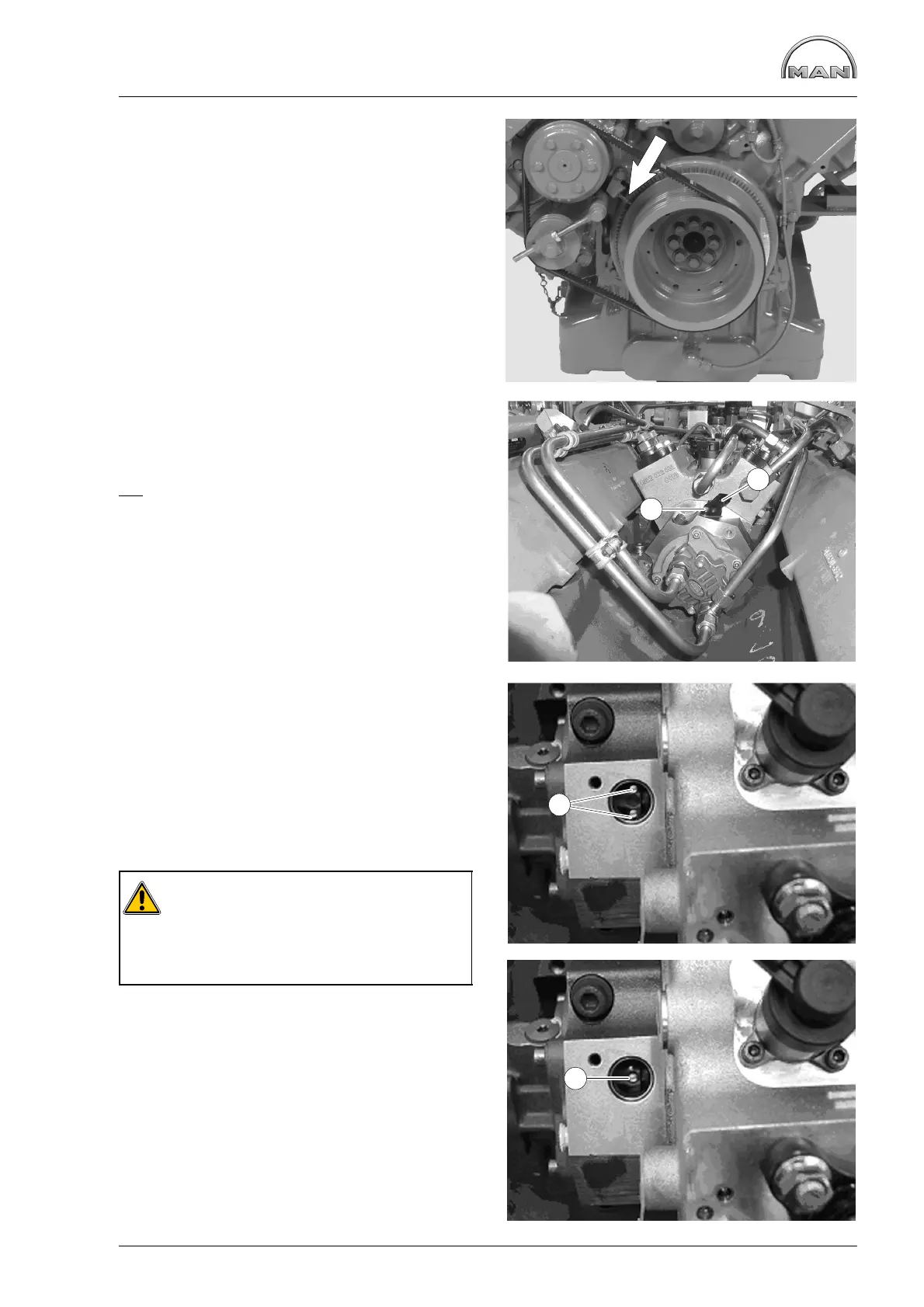
Fig. 5
The indicator (arrow) must then be aligned so that
its measuring edge points exactly to the “TDC”
mark on the scale disc.
Turn engine to ignition TDC 1.
Fig. 6
Pull the connector off the rpm sensor Á.
Unscrew the mounting bolt À of the rpm sensor Á
and pull out the rpm sensor.
No
marking may be visible.
Fig. 7
If the engine is now turned back to 69° before
TDC, 2 markings À must be visible.
If both markings are visible, then fit the rpm sensor
and tighten the mounting bolt with 9 Nm.
Reconnect the control unit.
Fig. 9
Caution:
If only 1 marking is visible, the high−pres-
sure pump has been fitted and twisted by
180° towards ignition TDC engine cylin-
der 1.
In this case, the high-pressure pump has to be re-
moved.
2
1
1
1
 Loading...