5
6
7
8
Removing and installing valves
88
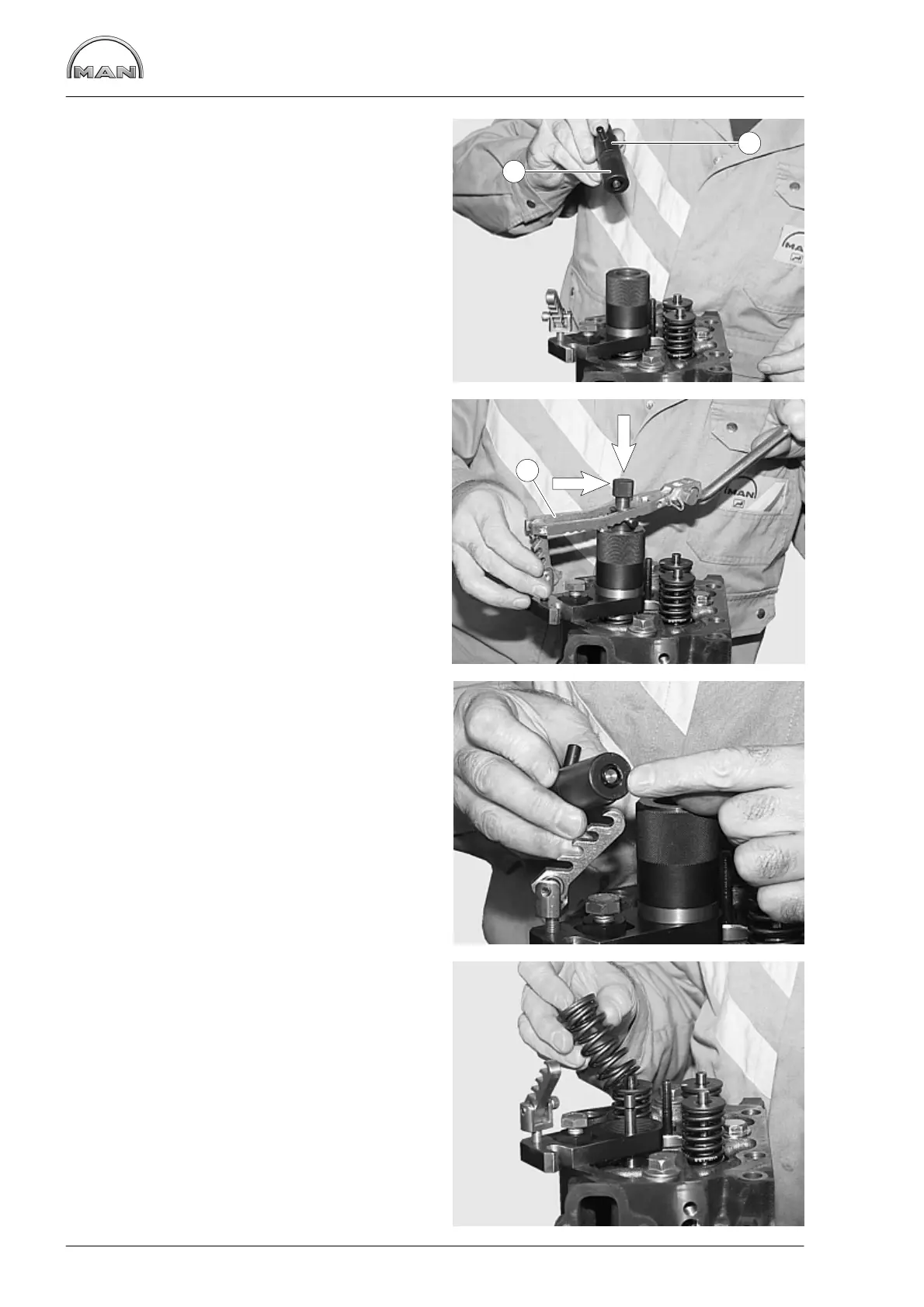
Fig. 5
Feed mounting cartridge Æ with sleeve È (small
dia.) into the guide sleeve and using the knurled
grip insert the holder into the joint between the re-
taining wedges.
Fig. 6
Attach pressure fork Ä and press down as far as
possible with the mounting cartridge.
Press the knurled grip (arrow) down, turning a little
if necessary.
Fig. 7
Release the pressure fork slowly. The retaining
wedges must now be in the mounting cartridge.
Fig. 8
Remove the guide sleeves and the valve spring.
Remove the anchor plate and attach it for removal
of the next valve spring.
7
9
5
 Loading...