2-63
GRT8100 SERVICE MANUAL HYDRAULIC SYSTEM
Published 3/26/2018, Control # 596-05
RANGE SHIFT/PARK BRAKE MANIFOLD
VALVE
Description
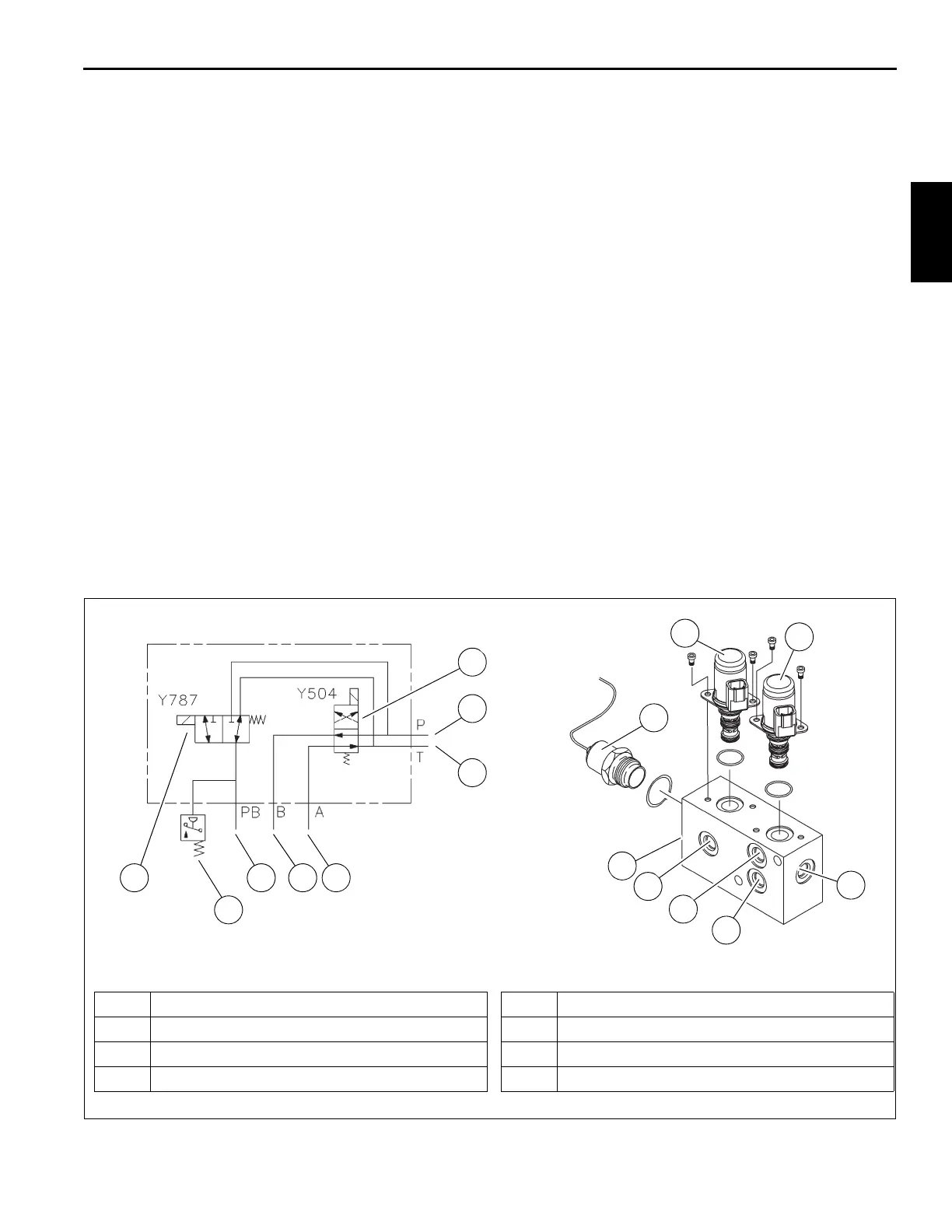
The parking brake/range shift manifold valve controls the
flow of oil to the parking brake, hi-low range and axle
disconnect actuators by the use of two solenoid valves (see
Figure 2-34). The valve is located on the center of the carrier
frame near the turntable bearing (Figure 2-17). Pressure is
supplied to the valve from the transmission charge pump.
The parking brake solenoid valve is a two-position, three-
way valve. In its de-energized position, the inlet port is
blocked and the parking brake actuator is drained to the
reservoir. When the solenoid is energized, the reservoir port
is blocked and pressurized oil is directed to the actuator,
engaging the parking brake.
The range shift solenoid valve is a two-position, four-way
valve. In its de-energized position, pressurized oil flows to
the “A” port of the range shift actuator, while the “B” port is
drained to the reservoir along with the axle disconnect
actuator for two wheel drive/high range. When the solenoid
is energized, pressurized oil is directed to the “B” port of the
range shift actuator and the axle disconnect actuator while
port “A” of the range shift actuator is drained to the reservoir
for four wheel drive/low range.
Maintenance
Removal
1. Tag and disconnect electrical connectors to the valve.
2. Tag and disconnect hydraulic hoses from the valve. Cap
or plug lines and ports.
3. Remove capscrews, lockwashers, flatwashers, and nuts
securing valve to the frame. Remove valve.
Installation
1. Secure valve to frame with nuts, flatwashers,
lockwashers, and capscrews. Torque capscrews - refer
to Fasteners and Torque Values, page 1-15 for proper
torque value.
2. Connect hydraulic hoses to ports on valve as tagged
during removal.
3. Connect electrical connectors to valve as tagged during
removal.
Functional Tests
1. Start and idle engine.
2. With unit on outriggers, check for proper two/four wheel
operation.
6697-1
FIGURE 2-34
1 Inlet Port (P)
2 Tank Port (T)
3 Work Port (A) - Range Shift Actuator
4 Work Port (B) - Range Shift Actuator
5 Work Port (PB) - Park Brake
6 Control Valve - Range Shift
7 Control Valve - Park Brake
8 Pressure Switch - Park Brake
Parking Brake/Range Shift Valve
1
2
345
6
7
8
1
2
3
4
5
6
7
8
8804-105

 Loading...


