2-61
GRT8100 SERVICE MANUAL HYDRAULIC SYSTEM
Published 3/26/2018, Control # 596-05
OUTRIGGER CONTROL MANIFOLD
Description
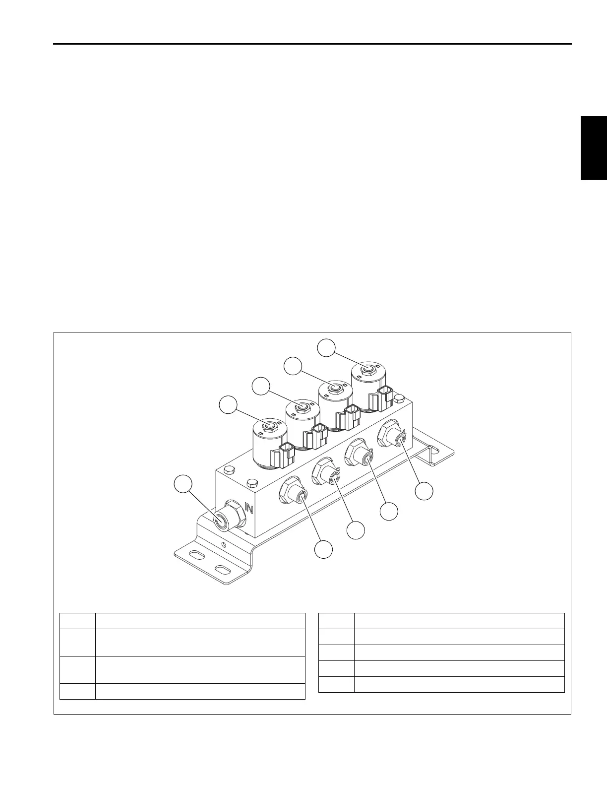
There are two outrigger control manifolds (Figure 2-32 and
Figure 2-33) utilized on the crane, one located on the front
outrigger box for controlling the front outriggers and one
located on the rear outrigger box for controlling the rear
outriggers (Figure 2-17). Each manifold consists of four
normally-closed, two-position, two-way solenoid valve
assemblies, one for each jack and extension cylinder.
Maintenance
Removal
1. Tag and disconnect the hydraulic lines to the solenoid
valves. Cap and plug all lines and openings.
2. Tag and disconnect the electrical connectors.
3. Remove the capscrews, hex nuts and washers securing
the manifold to the outrigger box. Remove the manifold.
Inspection
Visually inspect the valves and hydraulic connections for any
evidence of leaks or other damage. Check security of the
electrical connections. Inspect the wiring for any evidence of
cracks or breaks.
Installation
1. Position the manifold on the outrigger box and secure
with the washers, hex nuts, and capscrews. Torque
capscrews - refer to Fasteners and Torque Values, page
1-15 for proper torque value.
2. Connect the electrical connectors to the solenoids as
marked during removal.
3. Connect the hydraulic lines to the valves as marked
during removal.
Functional Check
Activate hydraulic system and cycle affected cylinder(s)
several times. Observe for proper functioning of affected
cylinder(s). Ensure solenoid valve hydraulic connections are
secure.
FIGURE 2-32
1 Control Valve - Right Front or Left Rear Jack
2
Control Valve - Right Front or Left Rear
Extension
3
Control Valve - Left Front or Right Rear
Extension
4 Control Valve - Left Front or Right Rear Jack
5 Work Port - Right Front or Left Rear Jack
6 Work Port - Right Front or Left Rear Extension
7 Work Port - Left Front or Right Rear Extension
8 Work Port - Left Front or Right Rear Jack
9 Inlet Port (IN)
1
2
3
4
9
5
6
7
8
8804-104
Outrigger Control Manifold

 Loading...


