5-9
GRT8100 SERVICE MANUAL HOIST AND COUNTERWEIGHT
Published 3/26/2018, Control # 596-05
HOIST ROTATION AND MINIMUM WRAP
INDICATOR SYSTEM
Description
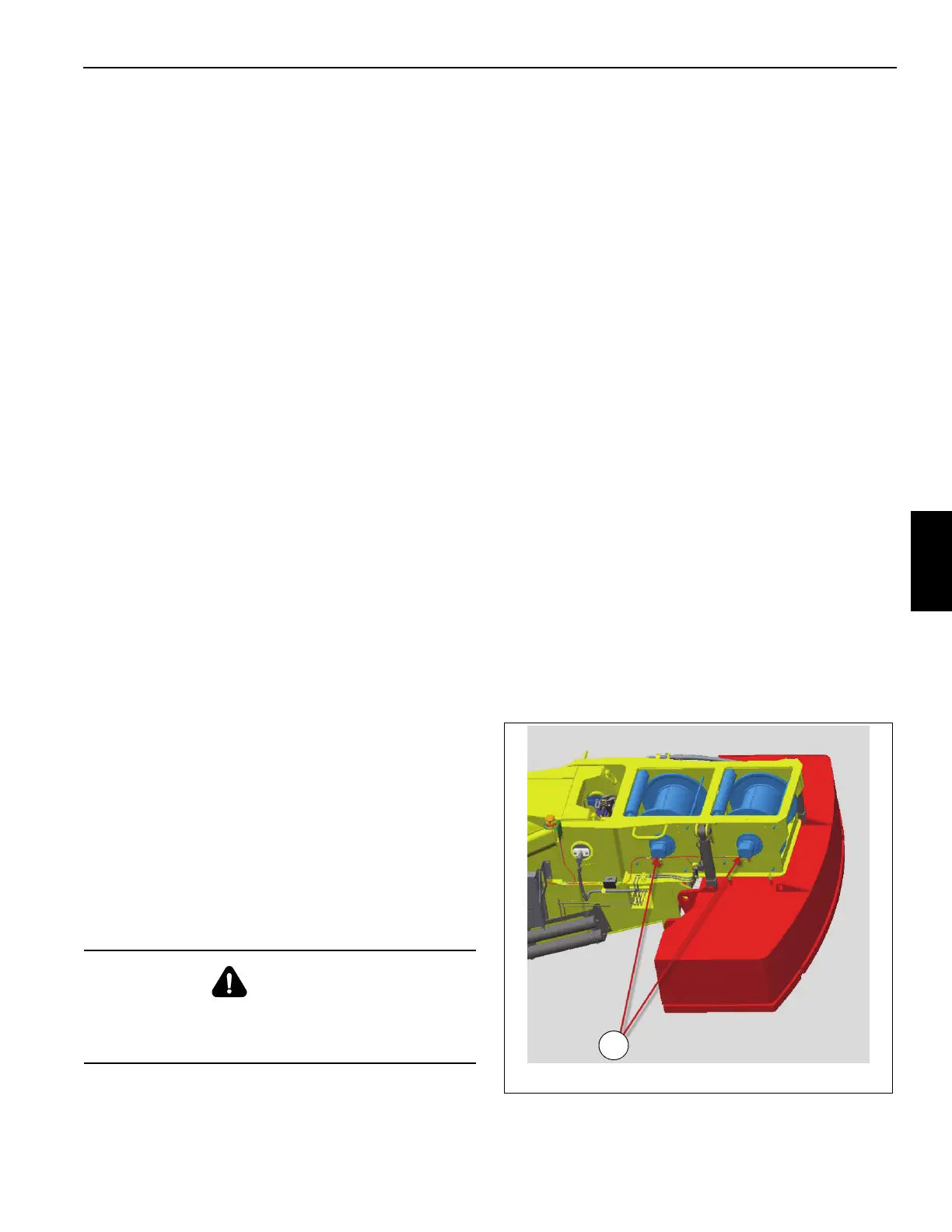
The main and auxiliary hoists are each equipped with an
encoder (Figure 5-5 and Figure 5-6) that is part of the hoist
rotation and minimum wrap indicator systems. The encoder
is mounted to the end of each hoist and senses the rotation
of the drum.
Hoist Rotation Indicator
The hoist rotation indicator system provides the operator
with a touch indication of the hoist drum rotation so he or she
knows if and at what speed the hoist drum is rotating. The
system also displays symbols on the rated capacity limiter
(RCL) display and crane control operation (CCS) display
indicating which hoist is operating and in what direction it is
rotating (hoist up or hoist down).
The hoist rotation indicator system uses a thumb thumper
solenoid to provide a physical indication to the operator of
hoist operation. Actuation of the thumb thumper is controlled
by the CAN bus modules from input supplied by the hoist
drum encoder. The pulsing thumb thumper solenoid is
located in the main and auxiliary hoist joystick handles and
provides feedback proportional to the hoist line speed by
pulsing the rubber button on top of the hoist joystick. The
thumb thumper solenoid will cease operation at high line
speeds to prevent damage to the solenoid.
Minimum Wrap Indicator
The minimum wrap indicator system uses the main and
auxiliary hoist encoders to indicate when there are three
wraps of cable remaining on the respective hoist. When
three wraps of cable are reached on the main or auxiliary
hoist, the crane control system will sound a buzzer in the
cab, cut-out the hoist down function, and display the
minimum wrap symbol on the RCL display to indicate that
three wraps of cable remain on the respective hoist. The
encoder must be properly adjusted for this system to function
properly. Refer to Adjusting Minimum Wrap Switch, page 5-
9.
Maintenance
General
Proper circuit operation can be checked for each individual
electrical component. If a malfunction occurs within the
system, repairs should be limited to finding and replacing the
faulty component(s). To determine which component is at
fault, refer to the troubleshooting section of your CAN bus
CD.
Adjusting Minimum Wrap Switch
1. Install hoist rope on the hoist.
2. Reeve hook block with four parts of line from hoist to be
adjusted.
3. Fully raise and extend boom.
4. Lower hook block until three wraps of rope remain on
hoist drum.
NOTE: If using synthetic rope, lower hook block until eight
wraps of line remain on hoist drum.
5. Remove four screws and cover from switch.
6. Rotate adjustment screw (2) until switch activates.
Service software may be used to monitor an indicator
light on the appropriate display.
7. Raise hook block until there are ten rope wraps on hoist
drum.
8. Lower hook block to verify lower limit switch actuates
with three rope wraps on hoist drum.
NOTE: If using synthetic rope, lower hook block to verify
lower limit switch actuates with eight rope wraps on
hoist drum.
9. Correct setting of switch if necessary.
10. Install cover and secure with four screws.
11. Repeat for auxiliary hoist.
DANGER
Disconnect the batteries before performing any
maintenance on this system. Serious burns may result
from accidental shorting or grounding of live circuits.

 Loading...


