4-19
Published 3/26/2018, Control # 596-05
GRT8100 SERVICE MANUAL BOOM
Disassembly
NOTE: Boom assembly must be rotated 180° (upside
down) before performing any assembly or
disassembly procedures.
Use the following procedures and refer to Figure 4-2 when
assembling the boom.
1. Remove boom following REMOVAL procedures outlined
in this section.
2. Position boom assembly upside down on adequate
supports.
3. Tag and remove all hydraulic tube assemblies from tele
stage selection manifold (39) and telescope cylinder (6).
Cap and plug all openings.
4. Remove four bolts (40), flat washers (10), lock washers
(11), and nuts (12) securing tele stage selection manifold
(39) to bottom rear of base section (1).
5. Remove four bolts (22) and hardened flat washers (33)
securing plate (35) to back of telescope cylinder (6) (see
Figure 4-3).
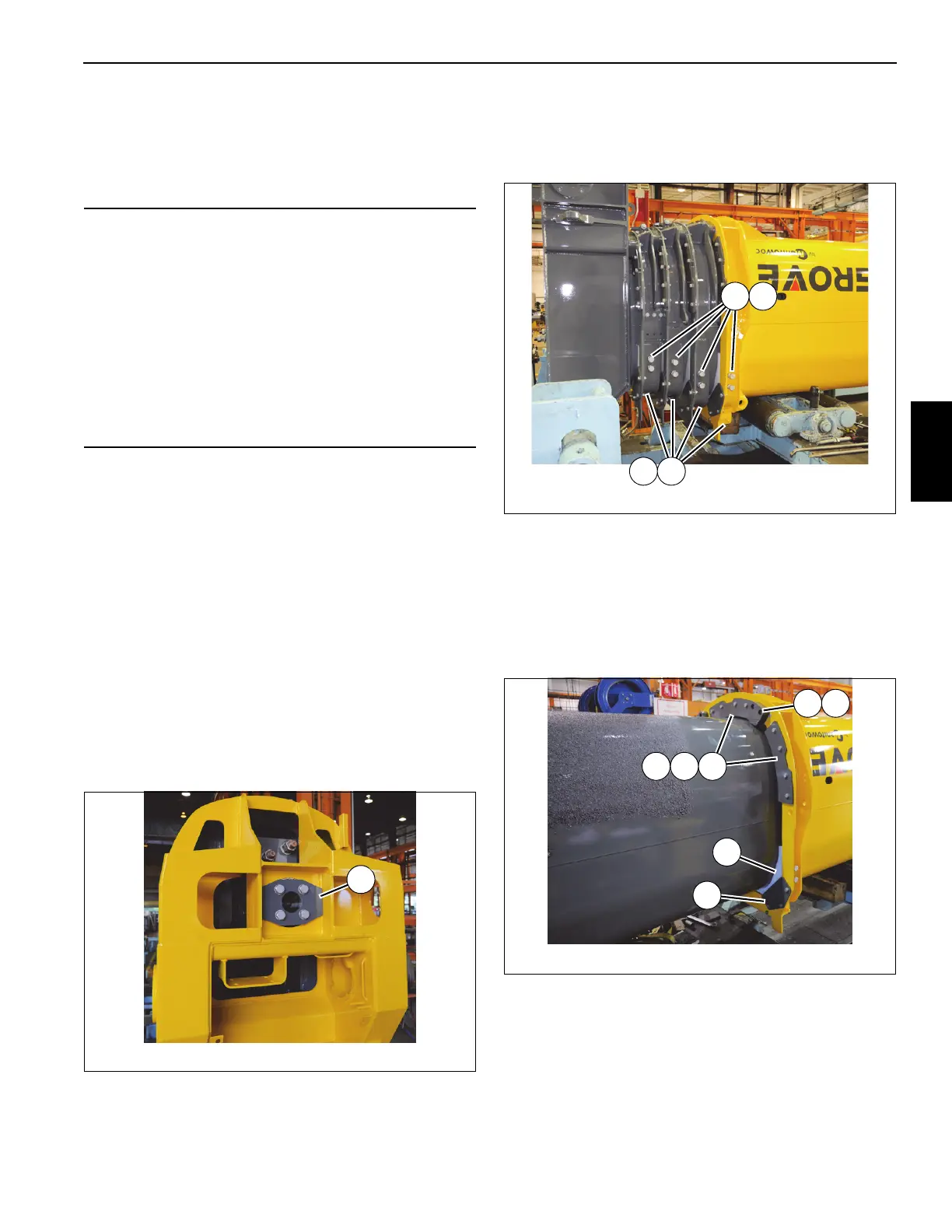
6. Working at front of base and tele sections 1, 2, 3, 4,
loosen two jam nuts (21) and bolts (22) on all upper wear
pads (19, 46, 78, 100) (left and right sides) (see
Figure 4-4).
7. Extend tele 1 (2) out from base section (1)
approximately one-quarter of its overall length.
8. Using an adequate lift and sling, slightly raise the front of
tele 1 (2).
9. Remove three capscrews (13) and flat washers (10)
securing keeper plate (20) to front of base section (1)
(left and right sides) (see Figure 4-5).
10. Remove wear pad assembly (19) from front of base
section (1) (left and right sides) (see Figure 4-5).
11. Slightly lower tele 1 (2).
12. Remove four bolts (13) and flat washers (10) securing
keeper plate (77) to front of base section (1) (left, right,
and center) (see Figure 4-5).
CAUTION
A rollover fixture with webbing is recommended to rotate
the boom sections. Chains are not recommended. If a
rollover fixture is not available, rotate the sections using
adequate support with webbing.
A secure fixture that will prevent damage to the boom is
recommended to stabilize and hold the boom from moving
during removal of the boom section(s).
When adjusting the extend and retract cables, hold the
cable end and turn the nut. Do not turn the cable. Turning
the cable while adjusting will result in damage or failure of
the cable.
FIGURE 4-4
8804-51
2221
21 22
FIGURE 4-5
8804-52
20
19
77
14 15
87
 Loading...


