BOOM GRT8100 SERVICE MANUAL
4-20
Published 3/26/2018, Control # 596-05
13. Remove two bolts (18) securing stop block (14) and
shim (15) to front of base section (1) (left and right sides)
(see Figure 4-5).
14. Remove wear pad (7) and two shims (8) from front of
base section (1) (see Figure 4-5).
15. Remove four capscrews (168) and hardened flat
washers (16) securing plate (167) to inside of base
section (1). Remove plates (167) (left and right sides)
(see Figure 4-6).
16. Remove tele 1 (2) from base section (1). Set tele 1 (2) on
adequate supports.
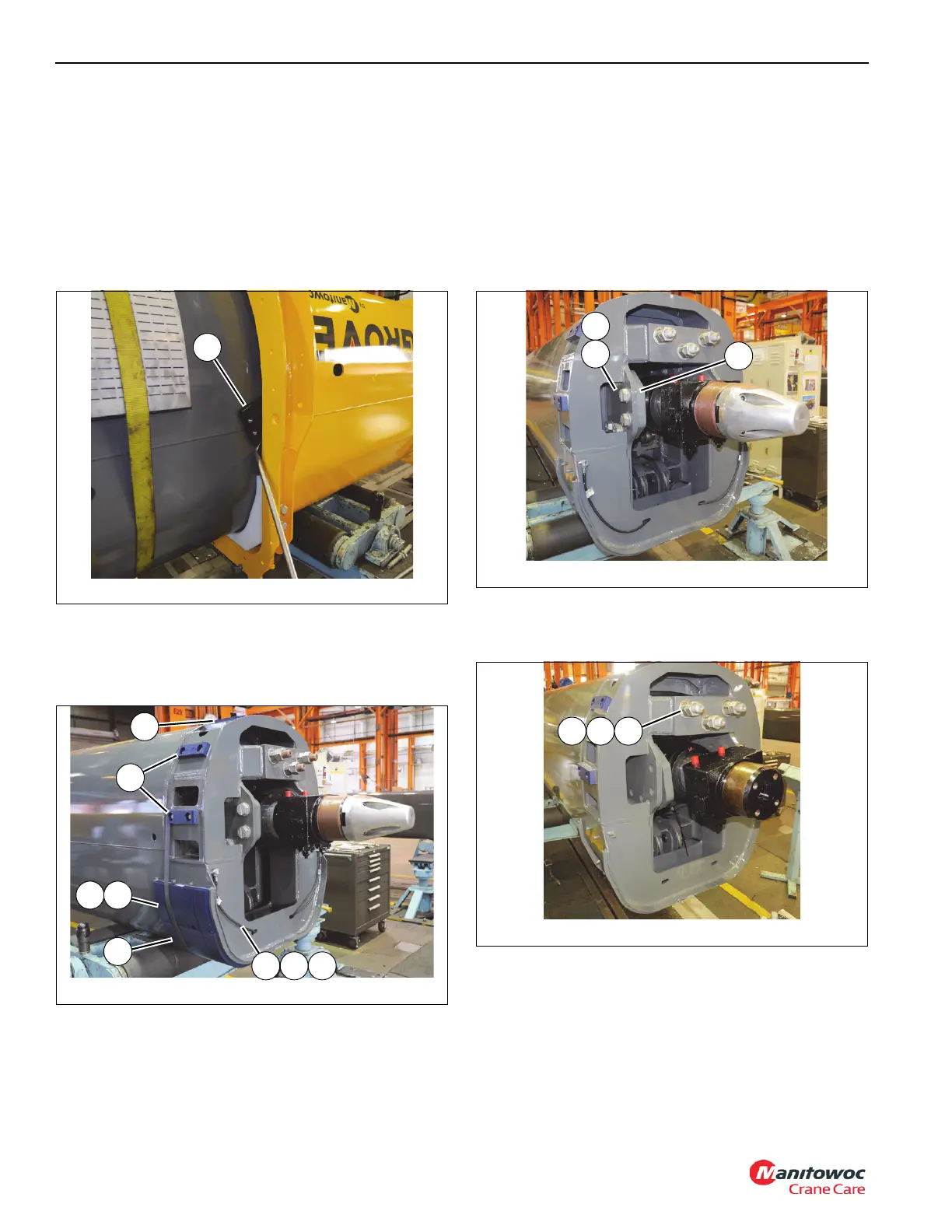
17. Remove wear pad (64) and shim (65) from rear of tele 1
(2) (left and right sides) (see Figure 4-7).
18. Detach grease hose assembly (66, 69, 70) from wear
pad (63) at rear of tele 1 (2) (left and right sides) (see
Figure 4-7).
19. Remove two capscrews (56) securing wear pad (2x-53)
and wear pad (4x-54) from rear of tele 1 (2) (see
Figure 4-7).
20. Remove six bolts (73) and hardened flat washers (72)
securing trunnion plate (71) to tele 1 (2) (left and right
sides) (see Figure 4-8).
21. Remove two nuts (60) and hardened flat washer (59)
securing each of the large bolts (3x-58) to rear of tele 1
(2) (see Figure 4-9).
22. Extend tele 2 (3) out from tele 1tele 1 (2) approximately
one-quarter of its overall length.
23. Remove four capscrews (22) and flat washers (50)
securing anchor weldment (47) to tele 1 (2) (see
Figure 4-10).
FIGURE 4-7
8804-53
65 64
64
69 7066
54
53
FIGURE 4-9
8804-47
60 59 58
 Loading...


