4-21
Published 3/26/2018, Control # 596-05
GRT8100 SERVICE MANUAL BOOM
24. Using an adequate lift and sling, slightly raise front of
tele 2 (3).
25. Remove three capscrews (13) and flat washers (10)
securing keeper plate (28) to front of tele 1 (2) (left and
right sides) (see Figure 4-11).
26. Remove wear pad assembly (46) from front of tele 1 (2)
(left and right sides) (see Figure 4-11).
27. Slightly lower tele 2 (3).
28. Remove four bolts (13) and flat washers (10) securing
keeper plate (9) to front of tele 1 (2) (left, right, and
center).
29. Remove two bolts (18) securing stop block (14) and
shim (15) to front of tele 1 (2) (left and right sides) (see
Figure 4-11).
30. Remove wear pad (44) and two shims (45) from front of
tele 1 (2) (see Figure 4-11).
31. Remove tele 2 (3) from tele section 1 (2). Set tele 2 (3)
on adequate supports.
32. Remove rear trunnion plate (71) from rear of telescope
cylinder (6) (left and right sides) (see Figure 4-12).
33. Remove wear pad (95) and shim (93) from rear of tele 2
(3) (left and right sides) (see Figure 4-13).
34. Detach grease hose assembly (66, 69, 70) from wear
pad (94) at rear of tele 2 (3) (left and right sides) (see
Figure 4-13).
35. Remove two capscrews (56) securing wear pad (6x-54)
to rear of tele 2 (3) (see Figure 4-13).
36. Remove bolt (58) from each of the three anchor blocks
(57) (see Figure 4-14).
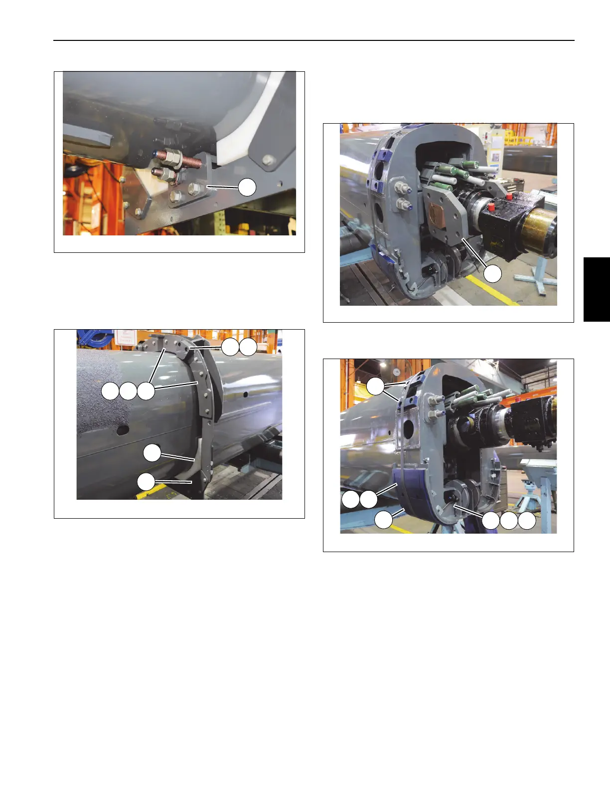
FIGURE 4-11
8804-54
28
46
9
1514
4544
FIGURE 4-13
8804-55
93 95
69 7066
94
54

 Loading...


