2-3
GRT8100 SERVICE MANUAL HYDRAULIC SYSTEM
Published 3/26/2018, Control # 596-05
DESCRIPTION
This section describes the hydraulic system, the
components which make up the hydraulic system, and the
components dependent upon the hydraulic system for their
operation. This includes descriptions of the supply pressure
and return hydraulic circuit, hydraulic pumps, all hydraulic
valves, and all hydraulic cylinders. Detailed descriptions and
operation of individual hydraulic circuits are discussed within
their individual sections as applicable. A complete hydraulic
system schematic showing all options is at the back of this
manual.
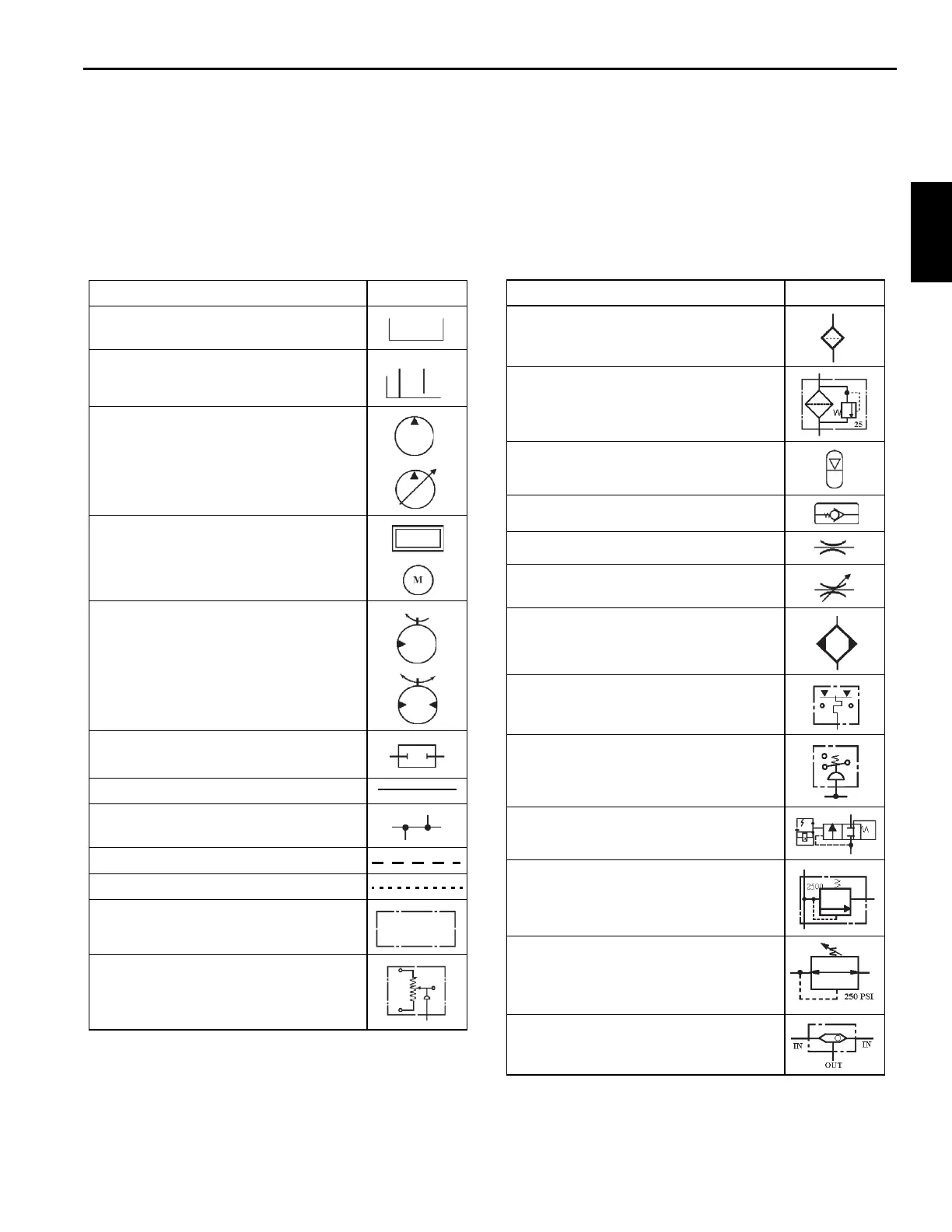
HYDRAULIC SYMBOLS
Description Symbol
Hydraulic Reservoir - Stores, cools, and
cleans machines hydraulic fluid supply.
Hydraulic Return Lines - Terminated at (1)
below fluid level (2) above fluid level.
Hydraulic Pump - (1) fixed displacement
(2) variable displacement.
Power Source - Powers hydraulic pump
(1) combustion engine, (2) electric motor.
Hydraulic Motors - (1) unidirectional,
(2) bidirectional.
Pump Disconnect - Disconnects pump
from power source.
Continuous Line - Supply or return lines.
Connecting Lines - Branch lines
connected to main line.
Dashed Line - Pilot pressure.
Dotted Line - Case drain or load sense.
Chain Line - Enclosure of two or more
functions contained in one unit.
Pressure Transducer - Hydraulic/
electrical located in lift cylinder circuit for
cranes RCL circuit.
Filter - Removes contamination from
hydraulic fluid.
Filter with Bypass Valve - Bypass valve
allows hydraulic fluid to bypass the filter if
the filter becomes clogged.
Accumulator - Used to either develop flow
or absorb shock.
Check Valve - Creates back pressure.
Orifice - In-line fixed restriction.
Adjustable Orifice - In-line restriction used
for control device.
Hydraulic Oil Cooler - Cools hydraulic
fluid.
Temperature Switch - Regulates the
hydraulic fluid temperature.
Hydraulic Pressure Switch - Senses
hydraulic pressure to energize electrical
components.
Flow Switch - Illuminates indicator light to
indicate a fault.
Relief Valve - Protects system from being
over pressurized.
Pressure Reducing Valve - Regulates
maximum pressure.
Shuttle Valve - Used to direct maximum
pressure to components.
Description Symbol
 Loading...


