6-21
Published 3/26/2018, Control # 596-05
GRT8100 SERVICE MANUAL SWING SYSTEM
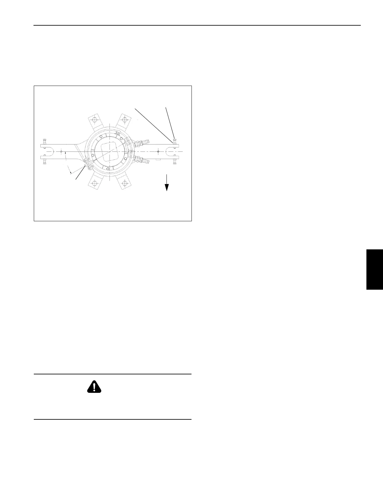
3. Ensure the anti-rotation pin in the bottom of the electrical
swivel base is aligned with the mounting hole in the
bracket on the water swivel case Figure 6-6.
NOTE: Allow a 1/32” max gap between bolt and retaining
lug on frame. Do not tighten bolt against lug.
4. Apply medium strength Loctite to set screws securing
electrical swivel to center post. Torque 45 to 55 lb-in (5
to 6 Nm). Tighten jam nuts.
5. Connect wiring harness connectors to receptacles on
cab bulkhead mounting plate as tagged during removal.
6. Unbundle wires of collector core wiring harness. Install
pins, with wire attached, to connector as tagged during
removal.
7. Plug connector into carrier wiring receptacle, connect
wires as tagged during removal. Install yellow ground
wire to connector mounting bracket on carrier frame
using the bolt and star washers taken of at removal and
refer to Grove Engineering Specification 6829100386 for
proper electrical termination of grounds.
8. Install clamp securing harness to retainer plate on
bottom of hydraulic swivel assembly.
9. Connect batteries.
10. Activate all systems, cycle all functions, and observe for
proper operation. Adjust slew angle in accordance with
Slew Angle Verification, page 6-21.
Preventive Maintenance
It is recommended a normal inspection of the electrical
swivel collector ring and brush assembly be established. An
example of this could be at approximately 100 to 150 engine
operating hours. When this time limit is reached, perform the
following.
1. Check collector ring and brush assembly for any
corrosion, pitting, arcing, and wear.
2. Check collector ring setscrews are tight.
3. Check brush and arm assembly springs. Ensure they
are holding brushes firmly against the collector rings.
Slew Angle Zero Adjustment Procedure
1. Rotate superstructure over front and engage lock pin.
NOTE: Refer to Hirschmann Rated Capacity Limiter
Operator’s Handbook for detailed instructions.
Complete the RCL console setup according to the
crane’s current operating configuration.
2. Select the Info icon.
3. Select the Info icon.
4. Enter authorization code 64356, then select return.
5. Select return until the slew adjustment screen is
displayed.
6. Select Auto 0 (zero) icon. Note indicator line moves to
zero on the bar graph on the slew adjustment screen.
7. Press ESC keypad button on RCL console.
Slew Angle Verification
1. Rotate superstructure over front and engage house lock
pin.
2. Set RCL console to read slewing angle as follows:
NOTE: Refer to Hirschmann Rated Capacity Limiter
Operator’s Handbook for detailed instructions.
• Complete the RCL console setup according to the
crane’s current operating configuration.
• Select Info icon.
• Select Info icon.
3. Verify angle indicated on console does not exceed ± 1.0
degree.
SWING LOCK PIN
Description
The purpose of the swing lock pin is to lock the
superstructure in position directly over the front for pick and
carry loads. The pin swing lock installation consists of a large
CAUTION
The slew potentiometer must be adjusted any time work is
done to the electrical swivel. Personnel injury or damage
to the machine may result.
FIGURE 6-6
Anti- Rotation
Pin
30°
Forward
Hex Nut
Capscrew
 Loading...


