4-29
Published 3/26/2018, Control # 596-05
GRT8100 SERVICE MANUAL BOOM
Installation
NOTE: The boom nose sheave shafts weigh
approximately 46 kg (100 lb) each. The boom nose
sheaves weigh approximately 7.7 kg (17 lb) each.
1. Slowly insert lower boom nose sheave shaft through
boom nose while adding weldment pin keepers,
spacers, shims, and boom nose sheaves following their
location noted during disassembly.
2. Slowly insert upper boom nose sheave shaft through
boom nose while adding spacers, shims, and boom
nose sheaves following their location noted during
disassembly.
3. Ensure end play is 1 mm to 2 mm on both upper and
lower boom sheave shafts. If additional shims are
needed, install them equally on both sides of the boom
nose.
4. Secure upper and lower boom nose shafts to the boom
nose using holder plates and capscrews.
5. Install the three lock hair pins into upper and lower parts
of boom nose, then secure with hitch pin clips.
Assembly
NOTE: The boom assembly must be rotated 180° (upside
down) before performing any assembly or
disassembly procedures.
NOTE: Apply medium strength thread locking adhesive/
sealant and primer to the threads of all attaching
hardware except cable ends and cable lock nuts.
NOTE: Apply multipurpose grease (MPG) to all wear
surfaces.
NOTE: Use standard Grade 5 and/or 8 torque values
specified in Section 1 of this manual unless
otherwise specified.
Use the following procedures and refer to Figure 4-2 when
assembling the boom.
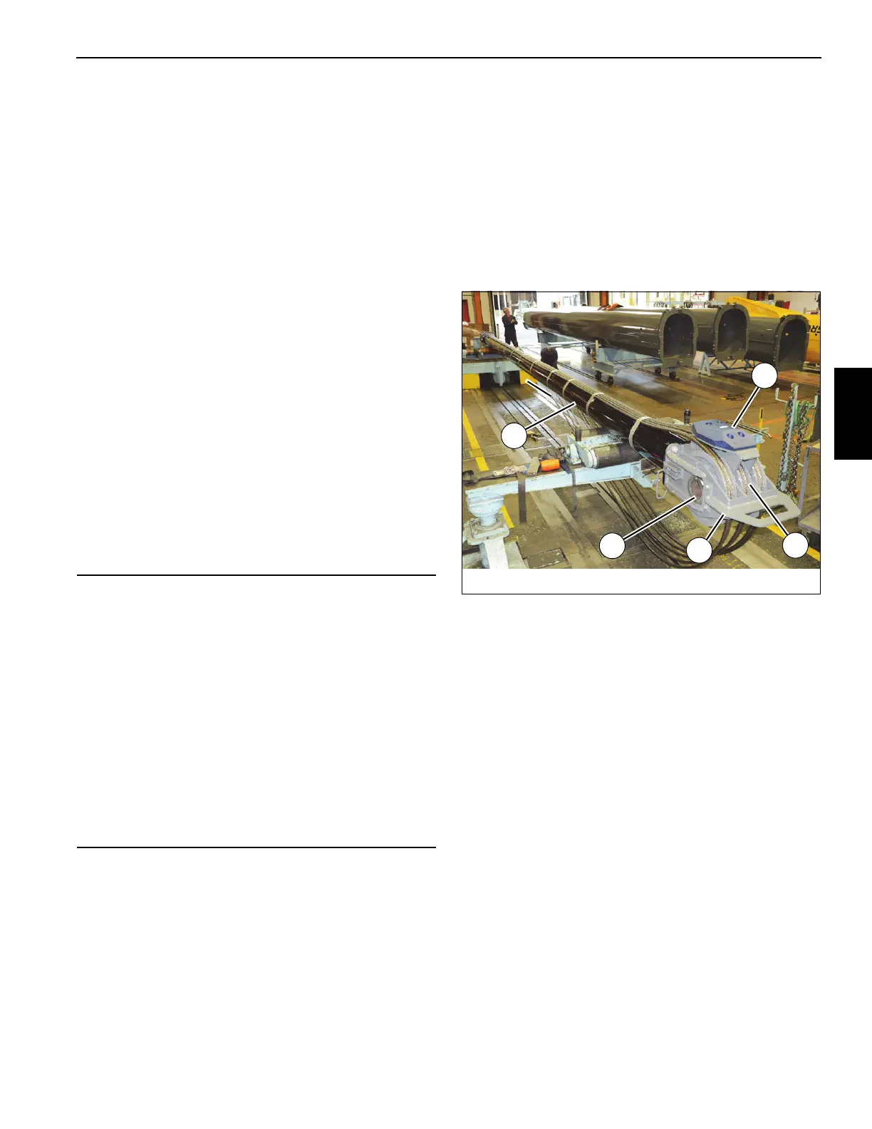
1. Position telescope cylinder (6) up side down on
adequate supports.
2. Attach telescope cylinder sheave mounting weldment
(133) to end of telescope cylinder (6) using four
capscrews (22) and flat washers (23) (see Figure 4-41).
3. Attach three sheave assemblies (134) to telescope
cylinder sheave mounting weldment (133) using hollow
shaft (136) and six spacers (135). Ensure machined
notches on ends of hollow shaft face towards boom tip
(see Figure 4-41). Secure hollow shaft (136) in place
using plate (137), two capscrews (111), and two
hardened flat washers (138) (see Figure 4-41).
4. Evenly lay out six tele 3 extend cables (139) beneath
telescope cylinder (6). Label cables on both ends with
sequence numbers (1-2-3-4-5-6) to prevent them from
being crossed during future installation.
5. Wrap six tele 3 extend cables (139) around sheave
assemblies (134) and bring all cable ends back to rear of
cylinder. Ensure cable ends with threads are hanging
underneath telescope cylinder. Use duct tape to secure
tele 3 extend cables to top of cylinder. Use special tool
(A) (p/n MT102668) to temporarily hold cable ends at
rear of cylinder (see Figure 4-41 and Figure 4-42).
CAUTION
A rollover fixture with webbing is recommended to rotate
the boom sections. Chains are not recommended. If a
rollover fixture is not available, rotate the sections using
adequate support with webbing.
A secure fixture that will prevent damage to the boom is
recommended to stabilize and hold the boom from moving
during removal of the boom section(s).
When adjusting the extend and retract cables, hold the
cable end and turn the nut. Do not turn the cable. Turning
the cable while adjusting will result in damage or failure of
the cable.
Install the cables in their natural untwisted condition. Do
not twist the cable. Twisting the cable will result in
damage or failure of the cable.
FIGURE 4-41
8804-1
134
6
136
142
134

 Loading...


