2-39
GRT8100 SERVICE MANUAL HYDRAULIC SYSTEM
Published 3/26/2018, Control # 596-05
VALVES
General
This subsection provides descriptive information for several
of the main hydraulic valves used on this crane. For a listing
of the valves, the circuit they are used in, and their physical
location, refer to Table 2-3. Refer to Figure 2-17 and
Figure 2-18 for valve locations.
The description of each valve given here is for the valve
itself. For information on how each valve functions in the
individual circuits, refer to the description and operation
procedures of that circuit.
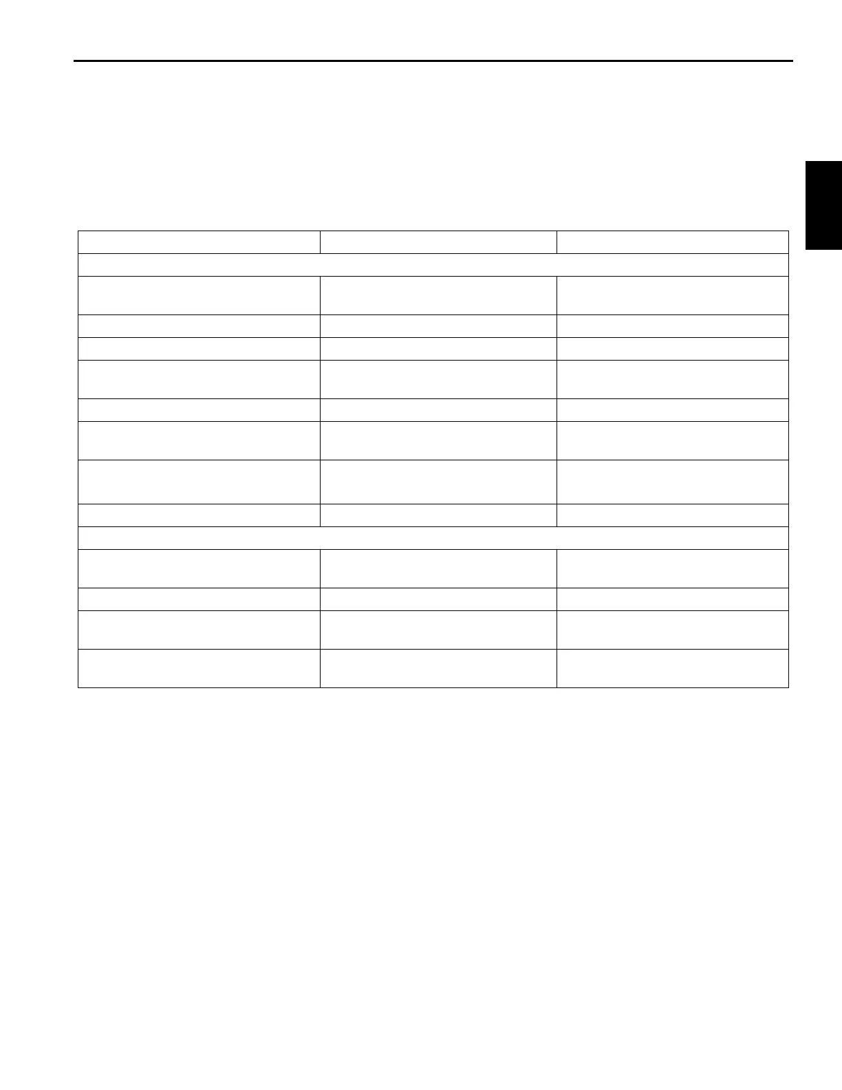
Table 2-3 Valve Usage Table
Item Circuit Location
Superstructure
Main Directional Control Manifold
Valves
Hoist/Lift /Telescope Right side superstructure
Swing Manifold Valve Swing Right side superstructure
Compact Manifold Valve Counterweight Removal/Cab Tilt Right side superstructure
Accessory Manifold Valve Front Steer/Swing Brake/Pilot Supply/
Fill Tube
Right side superstructure
Dual Accumulator Charge Valve Service Brakes Inside superstructure side plates
Telescope and Tele Fill Stage Select
Manifold Valve
Telescope Inside the rear of the boom assembly
Holding Valves Lift
Telescope
Lift cylinder (bolt on)
Telescope cylinder port blocks
Hydraulic Brake Accumulators Service Brakes Inside the superstructure side plates
Carrier
Carrier Combination Manifold Valve Load Sense Dump/Rear Steer/Axle
Lockout/Outriggers/Oil Cooler Fan
Inside turret on carrier
Outrigger Control Manifolds Outrigger Front and rear outrigger boxes
Cross Axle Differential Lock Valve Optional axle differential lock Front side rear center frame cross
member on carrier
Parking Brake/Range Shift Manifold
Valve
Parking Brake/Hi-Low Range Shift/
Axle Disconnect
Center of carrier frame near the
turntable bearing
 Loading...


