POWER TRAIN GRT8100 SERVICE MANUAL
7-2
Published 3/26/2018, Control # 596-05
Maintenance
Engine Removal
1. Set outriggers and position boom over the side.
2. Open and remove hood top door assembly.
3. Disconnect air filter tubing at engine and air cleaner.
Remove and lay aside.
4. Disconnect exhaust tubing at engine and muffler. Lay to
the side.
5. Tag and disconnect engine electrical harness connector
from carrier harness connector and battery cables.
6. Unbolt fuel filter and engine lubrication filter from frame
and lay on the engine.
7. Drain engine coolant system.
8. Drain engine lubrication system.
9. Drain transmission/torque converter oil system.
10. Remove engine hood assembly and pump cover from
machine.
11. Disconnect and remove drive shaft(s) between trans-
mission/torque converter and axle(s). Refer to Drive
Shafts, page 7-23 in this Section.
12. Tag and disconnect all lines from the radiator. Discon-
nect coolant level sensor harness from engine harness.
Tie up excess harness so it is out of the way. Remove
radiator. Refer to Radiator Removal and Installation,
page 7-19 in this Section.
13. Tag and disconnect all lines and tubing from engine,
transmission/torque converter, and all other compo-
nents.
NOTE: Engine and transmission/torque converter assem-
bly weighs approximately 1266 kg (2790 lb).
14. Attach a lifting device to engine capable of supporting
weight of engine and transmission/torque converter.
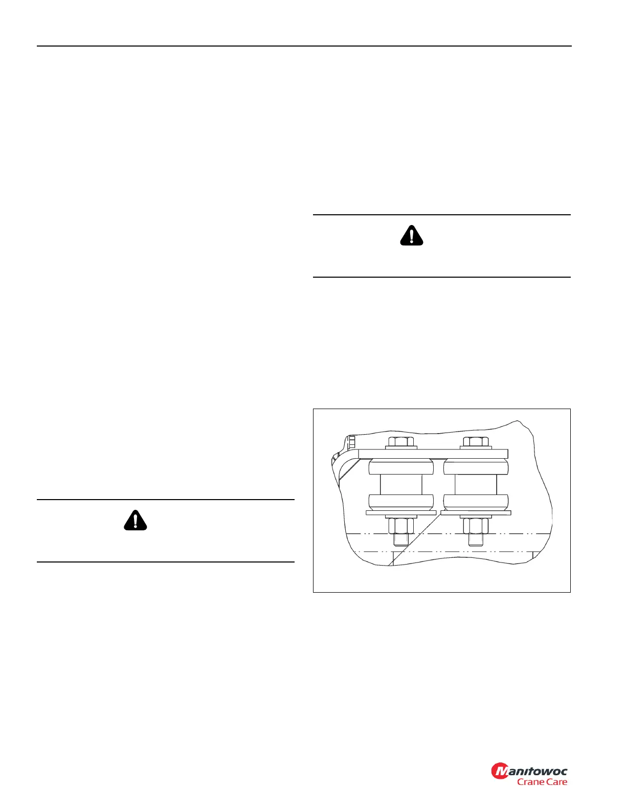
15. With lifting device supporting weight of engine, remove
two bolts, four flat washers, two lock washers, and two
nuts securing front of engine to frame (see Figure 7-2).
Remove two 2-piece isolator mounts, two capscrews,
two nuts, and two dock washers, and four washers
securing each side of transmission/torque converter to
frame (see Figure 7-1).
16. Using lifting device, lift engine and transmission/torque
converter as an assembly from the crane.
17. If a new engine is installed, remove all components, fit-
tings, etc., from old engine and install them on new
engine in same locations.
NOTE: Ensure same grade hardware, torque values, and
Loctite as were installed by the factory are used.
Engine Installation
NOTE: Use same grade hardware, torque values, and
Loctite used by factory.
1. With all components and fittings installed on the new
engine, lift the engine into the crane.
2. With engine in position, secure each side of transmis-
sion/torque converter with two 2-piece isolator mounts,
two capscrews, two nuts, and two dock washers, and
four washers (see Figure 7-1). At front of the engine,
secure engine mount to frame with two bolts, four flat
washers, two lock washers, and two nuts (see
Figure 7-2).
DANGER
Lifting device must be able to support combined weight of
engine and transmission.
DANGER
Lifting device must be able to support combined weight of
engine and transmission.

 Loading...


