HYDRAULIC SYSTEM GRT8100 SERVICE MANUAL
2-38
Published 3/26/2018, Control # 596-05
Checking/Setting the Axle Lockout Circuit
Pressure
1. With the engine off, install a pressure check diagnostic
coupler (9999101806) with gauge onto the diagnostic
nipple at G3 port of the carrier combination valve (see
Figure 2-14).
2. Start engine and let idle. Do not run any functions. Turn
the axle lockout pressure reducing valve integrated in
the carrier combination valve (see Figure 2-15)
clockwise to increase or counter-clockwise to decrease
so that a gauge pressure of 100 ±25 psi (7 ±2 bar) is
achieved.
3. Stop engine. Remove diagnostic coupler.
Checking/Setting the Luffing Jib Pressure
1. With the engine off, install a pressure check diagnostic
coupler (9999101806) with gauge onto the diagnostic
nipple at the G port of the luffing jib valve (see
Figure 2-16)
2. If the cylinder is installed, go to step 3. If the luffing jib
cylinder is not
installed, plug the hoses.
3. Start engine and let idle. If the luffing jib cylinder is
installed, fully retract it first. Slowly actuate the luffing jib
lower function until full controller stroke is reached and
hold. Turn the luffing jib relief valve clockwise to increase
or counter-clockwise to decrease so that the gauge
pressure of 4000 ±100 psi (276 ±7 bar) is achieved (see
Figure 2-16).
4. Stop engine. Remove diagnostic couplers.
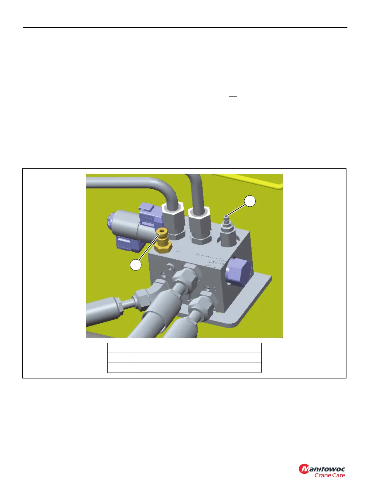
FIGURE 2-16
8804-72
Luffing Jib Valve
1 G port
2 Luffing jib relief valve
2
1

 Loading...


