HYDRAULIC SYSTEM GRT8100 SERVICE MANUAL
2-30
Published 3/26/2018, Control # 596-05
Checking/Setting the Pilot Supply Pressure
1. With the engine off, install pressure check diagnostic
quick disconnect (9999101806) with gauge onto test
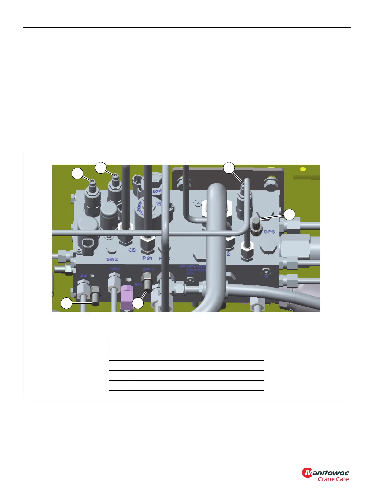
nipple at GP4 port of the front steer/swing brake/pilot
supply manifold (see Figure 2-9).
2. Start engine and allow it to idle, then turn the crane
function switch on.
3. Slowly actuate the lift down function and hold. Turn the
pilot supply pressure reducing valve (see Figure 2-9)
clockwise to increase or counter-clockwise to decrease
until a gauge pressure reading of 600 ±50 psi
(41 ±4 bar) is achieved.
4. Stop engine. Remove diagnostic couplers.
Checking/Setting the Front Steer Pressure
1. With the engine off, install pressure check diagnostic
quick disconnect (9999101806) with gauge onto test
nipple at GP6 port of the front steer/swing brake/pilot
supply manifold (see Figure 2-9).
2. Start engine and throttle up to full rpm. Fully turn the
steering wheel left or right against the axle stop and
hold. Turn the steering load sense relief valve (see
Figure 2-8) clockwise to increase or counter-clockwise
to decrease until a gauge pressure of 2800 ±50 psi
(193 ±4 bar) is achieved.
3. Stop engine. Remove diagnostic couplers.
Steer/Swing Brake/Pilot Supply Manifold (top)
1GP3 port
2GP4 port
3 Swing brake pressure reducing valve
4 Pilot supply pressure reducing valve
5 Accessory manifold pressure reducing valve
6GP6 port
FIGURE 2-9
8804-66
21
3
5
6
4

 Loading...


