BOOM GRT8100 SERVICE MANUAL
4-22
Published 3/26/2018, Control # 596-05
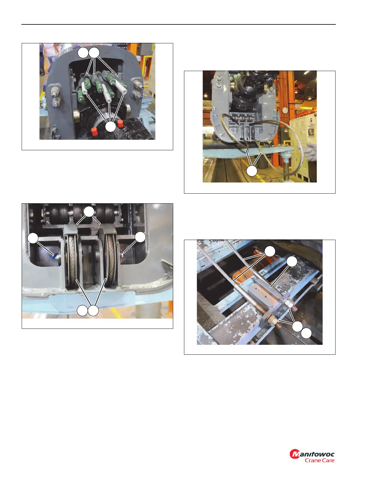
37. Remove two capscrews (62) securing keeper plate (61)
to each of the three anchor blocks (57). Remove the six
tele 3 extend cables (139) from anchor blocks (57) (see
Figure 4-14).
38. Remove two grease fittings (86) from shaft assemblies
(82) (see Figure 4-15).
39. Remove capscrew (85) and lock washer (28) securing
each shaft assembly (82) to rear of tele 2 (3) (left and
right sides) (seeFigure 4-15).
40. Remove shaft weldment (82), thrust washers (83),
sheave assembly (81), and guard weldment (84) (left
and right sides) (see Figure 4-15).
41. Remove capscrews (121), lock washers (11), and plates
(173) securing the anchor ends of the two tele 3 retract
cables (87) to rear of tele 3 (4) (see Figure 4-16). Detach
the two tele 3 retract cables (87).
42. Pull anchor ends of the two tele 3 retract cables (87)
through holes at rear of tele 2 (3) (see Figure 4-16).
43. Remove four nuts (49) and two washers (48) securing
the two tele 3 retract cables (87) to anchor weldment
(47) (see Figure 4-17).
44. Remove two capscrews (85) and flat washers (91)
securing shaft (89) in position at rear of tele 2 (3).
Remove shaft (89) and roller (90) (see Figure 4-18).
FIGURE 4-14
8804-43
61 57
58
FIGURE 4-15
8804-41
84
83 81
82
82
FIGURE 4-17
8804-42
47
48
49
87

 Loading...


