Published 4-20-2015, Control # 502-01 8-19
RT540E SERVICE MANUAL UNDERCARRIAGE
Caliper
1. Disconnect the hydraulic brake line from the inlet fitting
on the caliper. Cap or plug all openings.
2. Remove the linings as described previously.
3. Remove the bolts securing the caliper housing to the
mounting bracket. Remove the caliper housing from the
mounting bracket. If shims are used mark the position of
the shims.
Disassembly
Caliper
1. Remove the inlet fitting and o-ring from the cylinder cap.
2. Drain and discard the brake fluid.
3. Clean the outside of the housing with isopropyl alcohol.
Dry the housing with a clean cloth.
4. If installed, remove the bolts that secure the end plates
to the housing. Remove the end plates and linings.
5. Remove the pistons from the side of the housing
opposite the mounting plate according to the following
procedure.
a. Use a C-clamp to hold a 12.7 mm (0.5 in) block of
wood against two pistons on the mounting side of
the housing. Ensure the C-clamp is not in the area in
front of the piston bore (Figure 8-14).
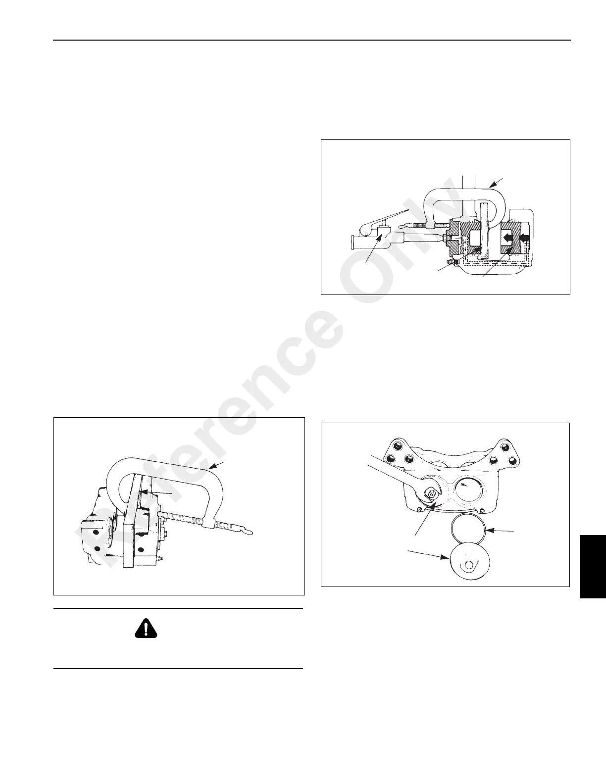
b. Apply compressed air to the inlet fitting to force the
pistons out of the other housing. If one piston comes
out before the other piston, put a piece of wood in
front of the piston that comes out first. Apply
compressed air to force the other piston out of the
housing (Figure 8-15).
c. Remove the wood block and the C-clamp from the
housing.
d. Remove the pistons from the bores that are
opposite from the mounting plate.
6. Remove the two bleeder screws from the housing.
7. Remove the cylinder caps from the housing using an
open end wrench. Remove and discard the O-rings
(Figure 8-16).
8. Remove the pistons from the mounting plate side of the
housing. Push on the ends of the pistons to force them
out of the disc side of the housing (Figure 8-17).
DANGER
Do not place hand in front of pistons when forcing them
out. Serious personal injury may occur.
Wood
Block
C-Clamp
FIGURE 8-14
C-Clamp
Piston
Air Gun
Wood
Block
FIGURE 8-15
Cylinder
Cap
O-Ring
FIGURE 8-16
Reference Only
 Loading...


