Published 4-20-2015, Control # 502-01 2-29
RT540E SERVICE MANUAL HYDRAULIC SYSTEM
2
4
5
3
1
6725
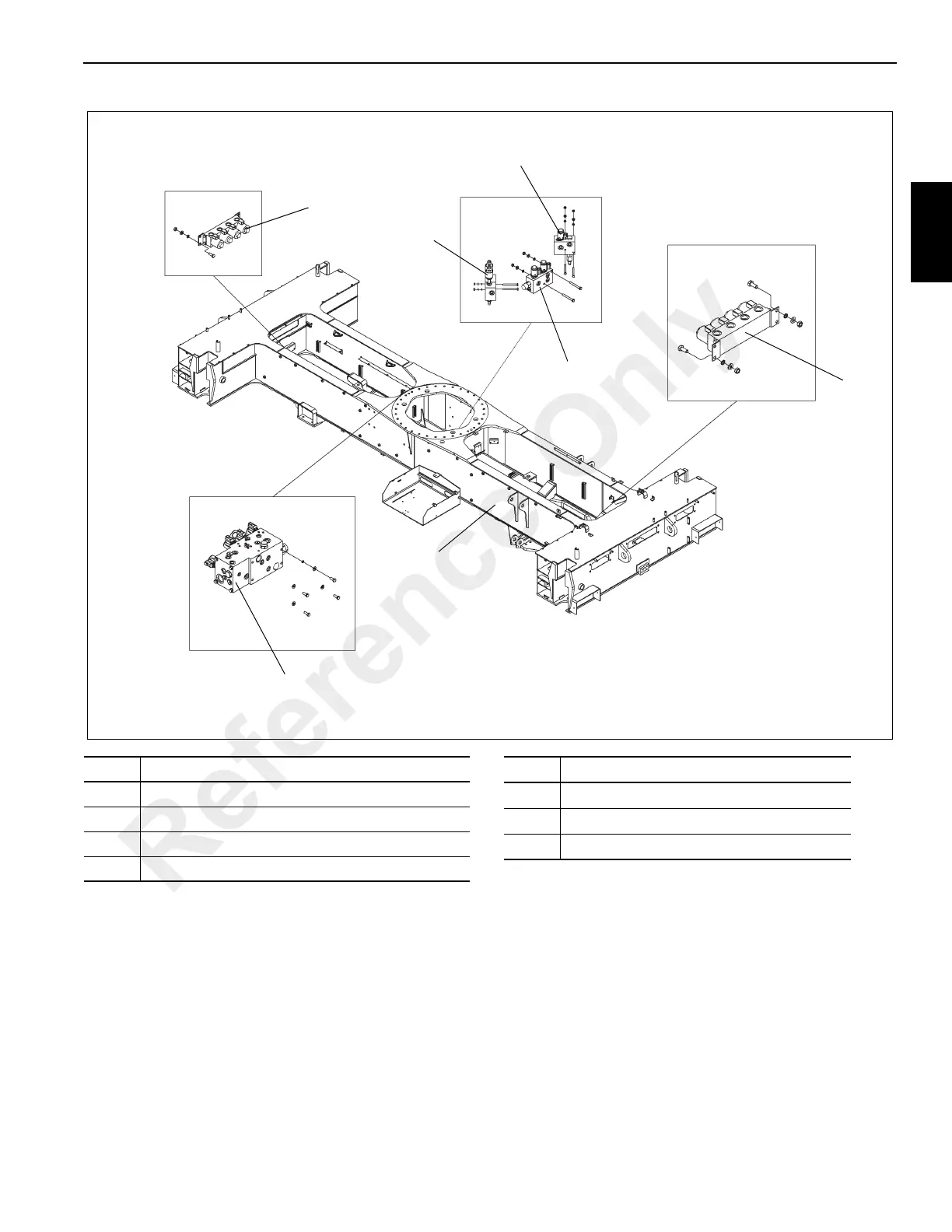
CARRIER
FIGURE 2-14 continued
6
7
Item Description
1 Front Outrigger Control Manifold
2 Outrigger/Rear Steer Valve
3 Differential Lock Valve
4 Park Brake Range Shift Valve
Item Description
5 Axle Lockout Valve
6 Rear Outrigger Control manifold
7Frame
Reference Only
 Loading...


