Grove Published 11-10-2014, Control # 524-00 8-3
RT880E SERVICE MANUAL UNDERCARRIAGE
Wheel Alignment Check Procedure
1. Check the axle for wheel alignment. The wheels are to
be straight ahead with no toe-in or toe-out. Adjust if nec-
essary by turning the tie rod ends in the direction neces-
sary.
2. Turn the wheels to the extreme left. Check the clearance
between the inside of the tire and the nearest object. If
the clearance is less than 1.0 in (25 mm), adjust the axle
stop to provide clearance. Do not adjust axle stop if
clearance is greater than 1.0 in (25 mm). With the axles
set at a 1.0 in (25 mm) clearance, check the steer cylin-
ders to see that they are not bottomed out. To check the
steer cylinders, remove the pin at the rod end and apply
pressure to move the cylinder rod. The cylinder rod
should travel a minimum of 0.12 in (3.0 mm).
3. Turn the wheels to the extreme right and repeat step 2
for the right side.
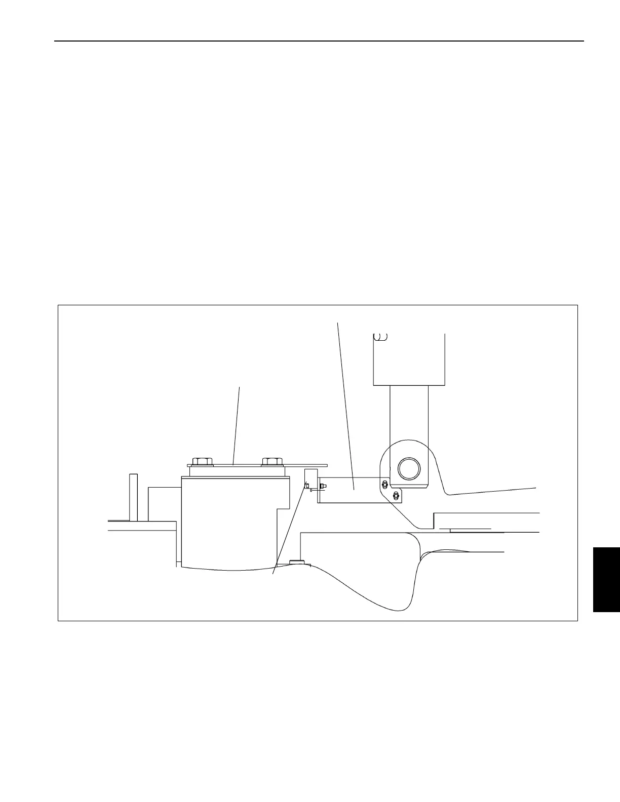
Rear Wheels Not Centered Switch Adjustment
Procedure
1. Ensure the wheels are straight ahead.
NOTE: Refer to (Figure 8-1) to perform the following
adjustments.
2. Ensure proximity sensor switch is centered in the slot of
the sensor plate bolted to the top of the axle trunnion
cap. Adjust by moving the sensor mounting bracket.
3. Ensure a maximum gap of 0.2 in (5 mm) exists between
the sensor switch and the sensor plate. Adjust by loos-
ening switch mounting bolts and moving switch up or
down on the mounting bracket. Tighten the mounting
bolts.
4. Turn the rear wheels to verify proper operation. Rear
Wheels Not Centered Light in cab should be out when
rear wheels are centered and the sensor switch is cen-
tered in the slot of the sensor plate.
FIGURE 8-1
Sensor Plate
Mounting Bracket
Sensor Switch
6393-1
 Loading...


