Grove Published 11-10-2014, Control # 524-00 8-21
RT880E SERVICE MANUAL UNDERCARRIAGE
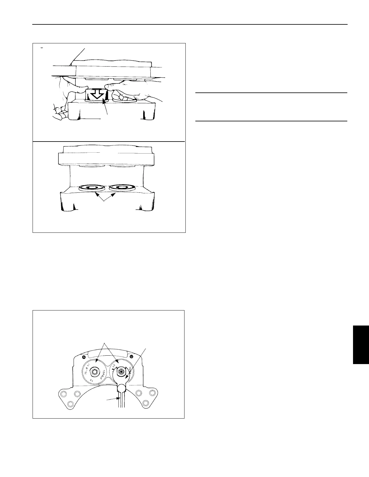
5. Install a new O-ring in the groove of the cylinder cap.
Ensure the O-ring is not cut by the threads on the cylin-
der cap.
NOTE: Apply extra grease on O-ring before installing cylin-
der caps. This will keep O-ring from catching on
threads as cylinder cap is threaded into housing.
6. Install the cylinder caps in the caliper housing. Tighten
the cylinder caps to 75 lb-ft (102 Nm) minimum as shown
in (Figure 8-26).
7. Install the bleeder screws in the housing. Tighten to 100
to 120 lb-in (11.3 to 13.6 Nm).
8. Install the O-ring and the inlet fitting in the cylinder cap.
Installation
Linings
1. Install the linings in the caliper housing.
2. Position the end plates on the housing and secure with
bolts. Apply Loctite® 271 or equivalent to the bolt
threads. Tighten the bolts to 165 to 210 lb-ft (224 to
285 Nm).
3. Ensure the linings move freely in the housing.
4. Bleed the brake system.
5. Apply and release the brakes three times to ensure the
caliper operates correctly. Check for fluid leaks. Ensure
the linings move freely.
Caliper
1. Position the caliper housing on the mounting bracket. If
shims were used, place them as marked during removal.
2. Secure the caliper housing with the bolts and tighten
them to 500 to 600 lb-ft (678 to 813 Nm).
3. Install the linings. Refer to Linings, page 8-21.
4. Ensure the housing is installed correctly on the mounting
bracket. The disc must be within ±0.06 in (±1.5 mm) of
being centered between the lining end plates.
a. To increase outboard clearance and decrease
inboard clearance, install a shim either between the
housing and mounting bracket or between the hub
and disc.
b. The shims must be steel, ground flat, and parallel
and must cover the entire mounting surface of the
hub or housing. The linings must move freely in the
housing and between the end plates (Figure 8-27).
Piston - - Use
Equal Pressure to
Push Piston into Bore
When Correctly
Installed the End of the
Piston is Even with the
Top of the Dust Seal
FIGURE 8-25
Torque
Wrench
Cylinder Cap - -
Tighten to 75 lb-ft (100
Nm) Minimum
1.25 Inch
Crow’s Foot
Wrench
FIGURE 8-26
CAUTION
Always replace both linings. If only one lining is replaced,
possible disc damage can occur.
 Loading...


