GROVE Published 10-21-2010, Control# 198-04 7-33
5540F/YB5515 SERVICE MANUAL TRANSMISSION AND TORQUE CONVERTER
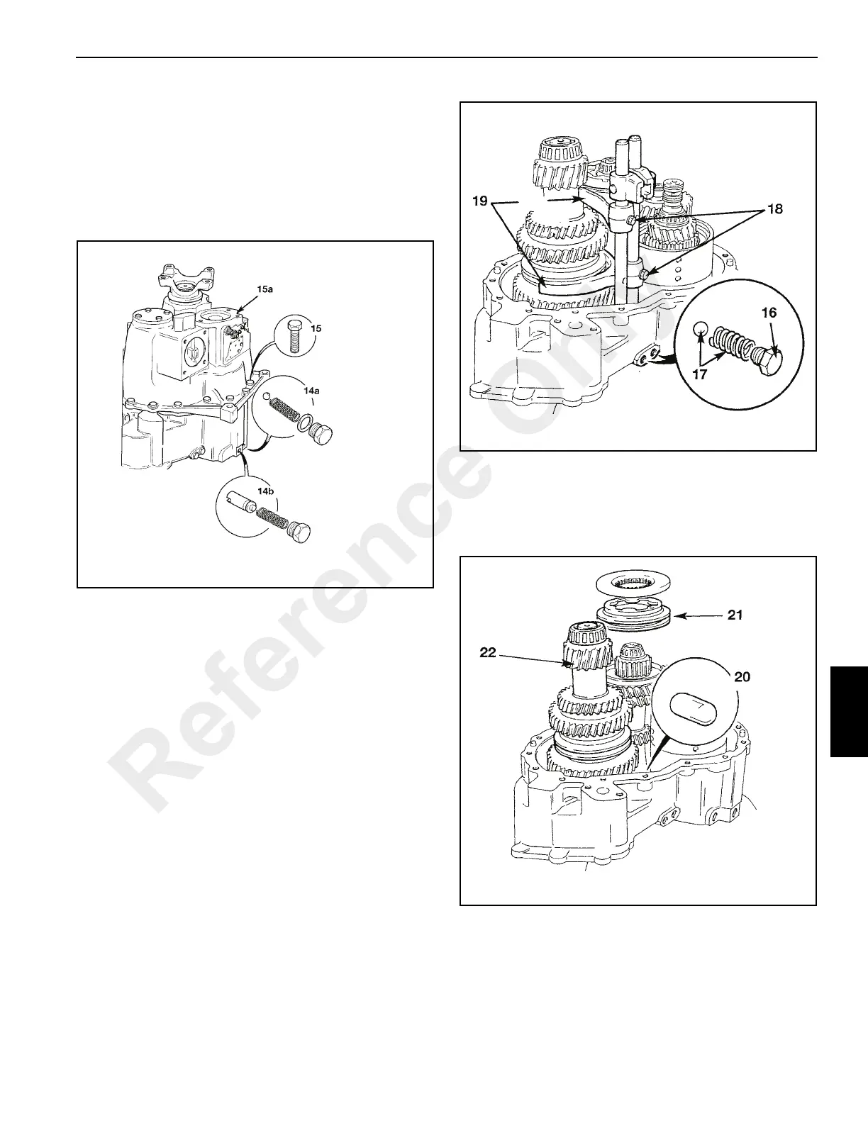
14. Remove the torque converter pressure relief valve ball
and spring assembly 14a (Figure 7-28). Remove the
torque converter pressure regulating valve spool and
spring assembly 14b.
15. Unscrew bolts 15 and lift off output end casing 15a. Be
sure to retrieve bearing outer cups from inside the
casing. Keep the cups together with their associated
bearing.
16. Unscrew selector detent plugs 16 (Figure 7-29).
17. Remove selector detent balls and springs 7.
18. Unscrew selector fork retaining screws 18 and lift out
selector rods.
19. Note that the selector forks 19 are not interchangeable.
Mark the forks to ensure they are replaced correctly.
Remove selector forks.
20. Push out the interlock plunger 20 (Figure 7-30) on
disassembly.
21. Lift off 3rd/4th synchro-hub 21. Note the positions for
refitting with mating cups.
22. Lift out layshaft assembly 22.
23. Remove idler gear upper thrust washers and bearing 23
(Figure 7-31). Keep the thrust washers and bearing
together.
24. Tilt mainshaft L to one side and lift off idler gear 24
together with its needle roller bearing 24a.
Reference Only
 Loading...


