TRANSMISSION AND TORQUE CONVERTER 5540F/YB5515 SERVICE MANUAL
7-34 Published 10-21-2010, Control# 198-04
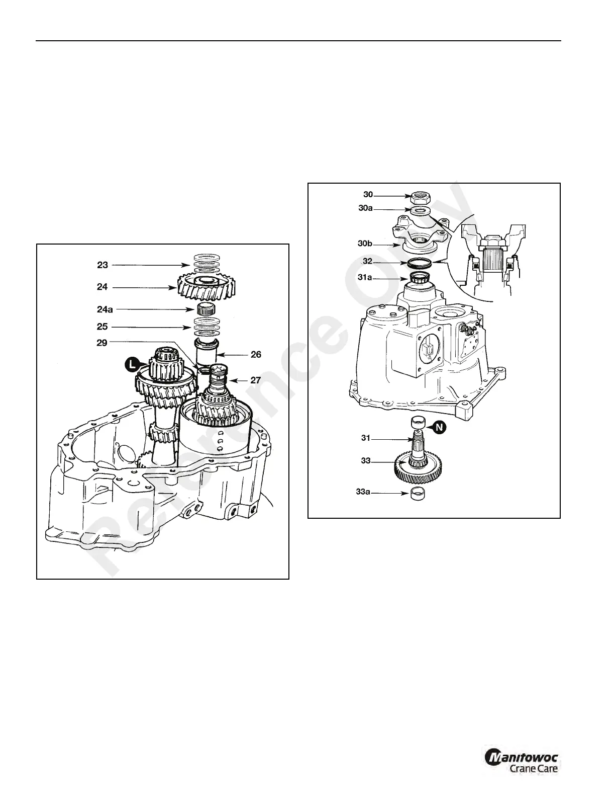
25. Remove idler gear lower thrust washers and bearing 25.
Keep the thrust washers and bearing together.
26. Lift off idler gear spacer 26.
27. Tilt mainshaft L to one side and lift out the reverser
assembly 27. Discard the piston rings seals.
NOTE: See Reverser Unit for reverser unit disassembly 8
and assembly procedures.
28. Remove mainshaft L.
29. The idler gear spindle is a press fit in the casing. Use a
suitable puller screwed into the 1/2 in B.S.P. hole in the
end of the spindle for extraction. Note that the spindle
should only be removed if it is damaged and is required
to be replaced.
30. Unstake the nut 30 (Figure 7-32). While holding the
output yoke, unscrew output shaft nut and remove the
washer 30a beneath. Support output shaft from beneath
and lift off the yoke 30b.
31. Withdraw output shaft assembly 31 and lift out outer
bearing 31a. Remove spacer N and retain for assembly.
32. Pry out oil seal 32 and discard.
33. Using a suitable puller, withdraw output shaft inner
bearing 33. Remove the mainshaft bearing outer cup
33a from the center of the output shaft transfer gear.
Mainshaft
34. Using suitable puller, pull off 3rd gear together with
synchro cup 34a, (Figure 7-33) gear 34b, spacer washer
34c, oil retention washer 34d and bearing 34e. Keep the
synchro hubs and cups in their original relationship.
35. Remove needle roller bearings 35.
Reference Only
 Loading...


