GROVE Published 10-21-2010, Control# 198-04 7-35
5540F/YB5515 SERVICE MANUAL TRANSMISSION AND TORQUE CONVERTER
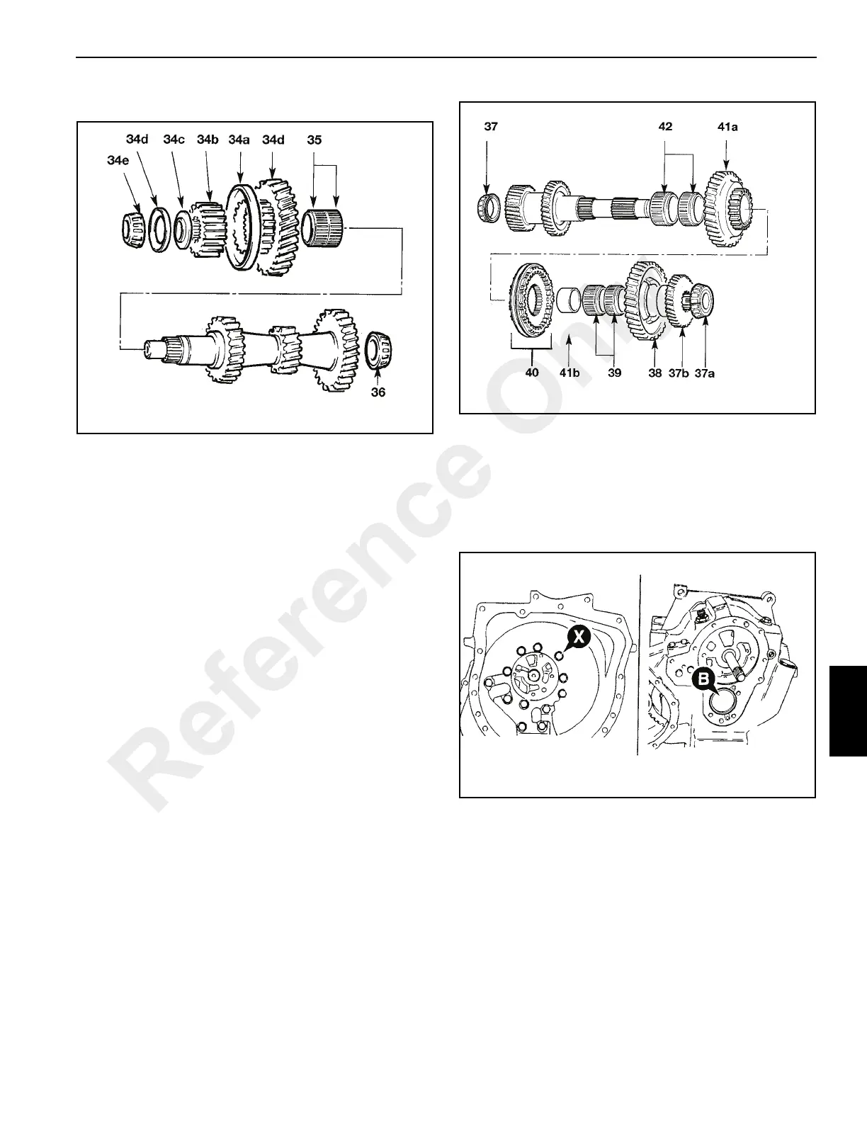
36. Remove bearing 36 from converter end of mainshaft
using press a suitable.
Layshaft
37. Remove the bearing 37 (Figure 7-34). Remove 4WD
transfer gear 37b and bearing 37a from layshaft. On
2WD machines a spacer is fitted in place of the transfer
gear.
38. Liftoff 1st gear 38.
39. Remove 1st gear needle roller bearings 39.
40. Note that the 1st/2nd synchro unit 40 is of a different
design to the 3rd/4th gear unit. There are components
which may be lost during removal unless care is taken.
Hold the unit together with the synchro cones on each
side and lift off. Keep the synchro cones, rings and hubs
in their original relationship.
41. Use a press to push off 2nd gear 41a, synchro assembly
40 and 1st gear needle roller track ring 41b.
42. Remove 2nd gear needle roller bearings 42.
Setting Ring Removal
The mainshaft and layshaft end float is controlled by a
threaded 'setting ring' screwed into the casing.
To enable access to the mainshaft setting ring the torque
converter housing must be removed. Undo the 12 fixing bolts
X (Figure 7-35) and remove the housing. The setting ring is
located at position B.
To enable access to the layshaft setting ring the bearing
cover must be removed. Undo the 4 fixing bolts Y,
(Figure 7-36) remove the cover and discard the gasket
beneath. The setting ring is located at position C.
If the bearings or shaft are to be renewed the associated
setting ring must be removed and discarded as follows:
Reference Only
 Loading...


