TRANSMISSION AND TORQUE CONVERTER 5540F/YB5515 SERVICE MANUAL
7-36 Published 10-21-2010, Control# 198-04
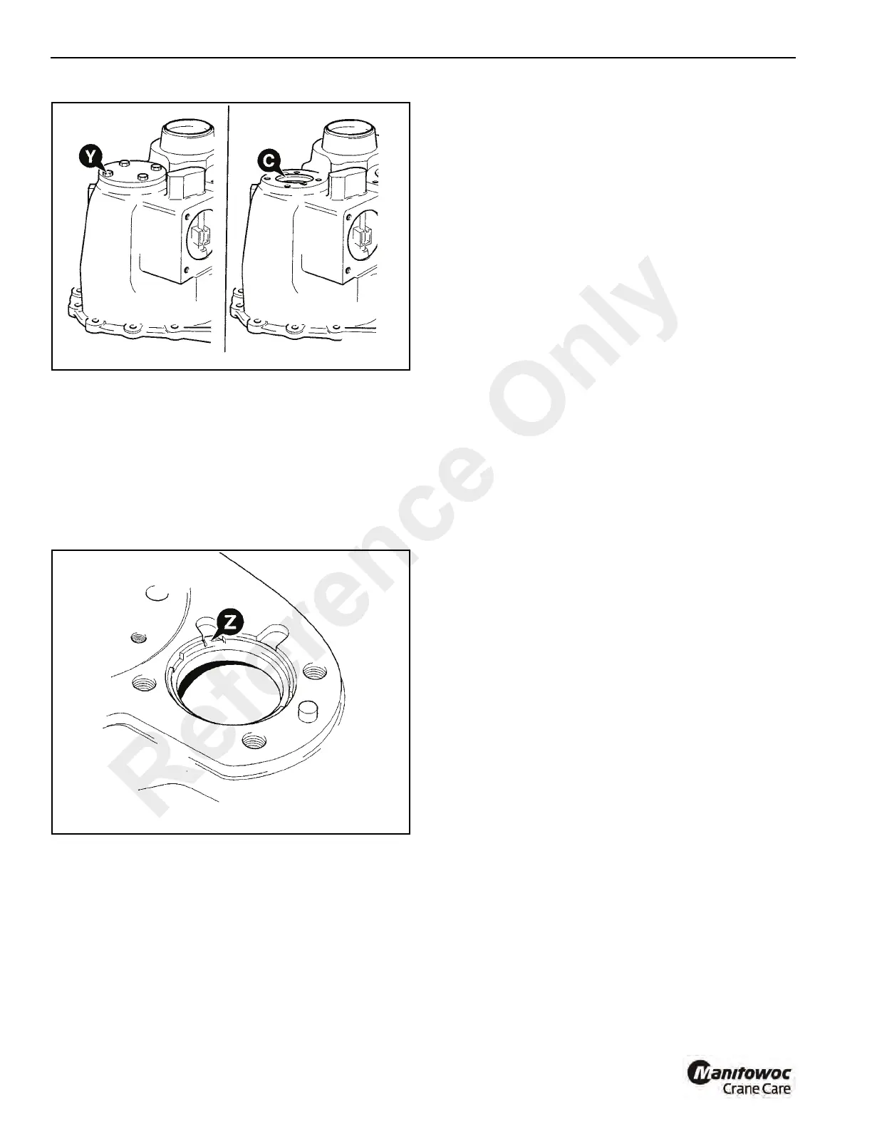
1. Carefully pry out the staked section of the ring Z
(Figure 7-37) clear of the casing.
2. Unscrew and discard the ring.
3. Be sure to remove any shards of metal that may have
fallen into the casing.
NOTE: Once removed, the setting rings must not be re-
used. Discard the ring and obtain a new one. Note
that the mainshaft and layshaft setting rings are not
interchangeable
Inspection
Before assembling the gearbox make sure that a thorough
inspection of all components is carried out. Remember that
although a failed component may be easy to identify, the
cause of that failure may be less easy to trace. It is also
possible that a failed component may have caused damage
to other areas of the gearbox.
1. Carefully remove all traces of gasket compound from
components as follows:
a. Front and rear casing mating faces.
b. Front casing and torque converter housing mating
faces.
2. Clean the inside of the casings using a suitable
degreasing agent.
3. Carefully inspect all gears, bearings and shafts for signs
of excessive wear or damage. If wear or damage is
evident, components must be renewed.
4. Make sure that all oil way cross drillings in the casings,
shafts and gears are clear and free from debris. Blocked
oil ways are a common cause of bearing failure. Use an
air line to blow through cross drillings.
NOTE: If failure of the reverser unit or hydraulic 2/4-wheel
drive unit is suspected, see the relevant
disassembly and assembly procedure in this
section.
1st/2nd Gear Synchromesh Unit
The 1st/2nd gear synchro unit must be checked for wear
before assembly as follows:(See Figure 7-38 thru
Figure 7-40)
1. Before dismantling the unit be aware that on
reassembly, the components must be kept in their
original relationships.
2. Disassemble the unit by removing the cones and rings
A1, A2 and B1, B2. Push off the sleeve C taking care to
retrieve the sets of balls D, poppets E and springs F.
3. Inspect the mating faces of cones and rings. The wear
indicator grooves X must still be visible. As a further
check, locate the cones and rings together (as shown at
Y) and measure the clearance between them using
feeler gauges. The clearance should be between 0.02 in
and 0.7 in for both A and B pairs. If either is out side
these limits then the complete synchro unit must be
renewed.
Reference Only
 Loading...


