AXLES/DRIVE SHAFTS/WHEELS AND TIRES 5540F/YB5515 SERVICE MANUAL
8-10 Published 10-21-2010, Control# 198-04
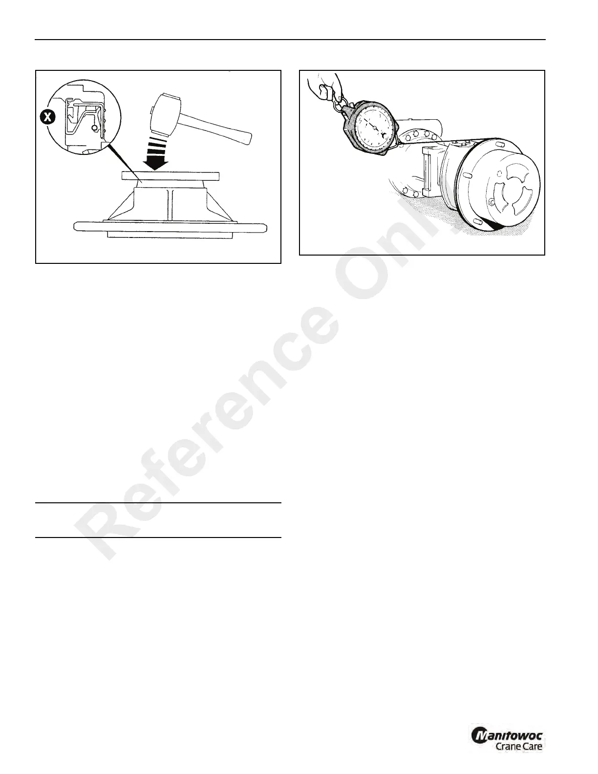
NOTE: After assembling the bearing carrier to the swivel
hub, make sure that there is sufficient clearance
between the hub and seal.
14. Install the cup of outer wheel bearing 10 Figure 8-8 into
the bearing carrier 8. Grease the bore of the
combination seal 9 and the surface of the stub.
15. Install the bearing carrier 8 onto hub swivel 3.
16. Lightly oil the bearing race of outer wheel bearing 11.
Install the bearing onto the axle arm. Rotate the carrier 8
(and therefore the bearing) during installation.
17. Assemble annulus ring 12 to annulus carrier 13. Secure
with retaining ring 14.
18. Install the annulus assembly in the same angular
position as removal (see Note before step 9 on
page 8-7) using new Verbus Ripp bolts 16. Do not fully
tighten the bolts but allow the bearing carrier to rock
slightly.
19. Check the bearing carrier rolling force:
a. Use a spring balance and cord wrapped around the
planet carrier bolts Figure 8-11. Pull the spring
balance so that the hub rotates. Do this several
times to set the seal and then record the reading.
b. Remove the planet gear carrier 18 Figure 8-8 and
tighten the new Verbus Ripp bolts 16 to 122 lb-ft
(166 Nm).
c. Repeat steps 19 and 19A and record the reading.
d. To get the rolling force, subtract the seal drag rolling
force (Step 19 A) from reading obtained at step 19C.
The result should be 3 to 34 lb. (1.4 to 15.3 kg).
If the resulting force is outside these limits check
that seal 19 is installed correctly and/or replace
bearings (6 and 11).
NOTE: A high rolling force reading may indicate that the oil
seal was damaged during installation.
20. Press the drive shaft thrust pad 17 (chamfered side
down) into the recess in planet gear carrier 18.
21. Install new planet gears 19 in place of any that were
removed (see Step 4 in Disassembly). Secure with
retaining ring 4 .
NOTE: Large radius end of the bearing core installs onto
the pin first.
22. Slide sun gear 20 onto the drive shaft and secure with
retaining ring 22.
23.
Install a new o-ring 23.
24. Inst
all planet gear carrier 18 onto bearing
carrier 8
turning it slightly to engage the gear teeth and aligning
the two tapped holes A Figure 8-8 in the planet gear
carrier. (The tapped holes are diametrically opposite one
another). Ensure that the gear carrier butts fully against
the bearing carrier.
NOTE: Do not strike the center of planet gear carrier 18
when installed, as this may dislodge drive shaft
thrust pad 17.
25. Install screws 24 and tighten to a torque of 41.3 lb-ft
(56 Nm).
26. Fill the axle hub with oil. See Preventative Maintenance,
Chapter 5.
CAUTION
Verbus Ripp bolts must NOT be reused.
Reference Only
 Loading...


