AXLES/DRIVE SHAFTS/WHEELS AND TIRES 5540F/YB5515 SERVICE MANUAL
8-12 Published 10-21-2010, Control# 198-04
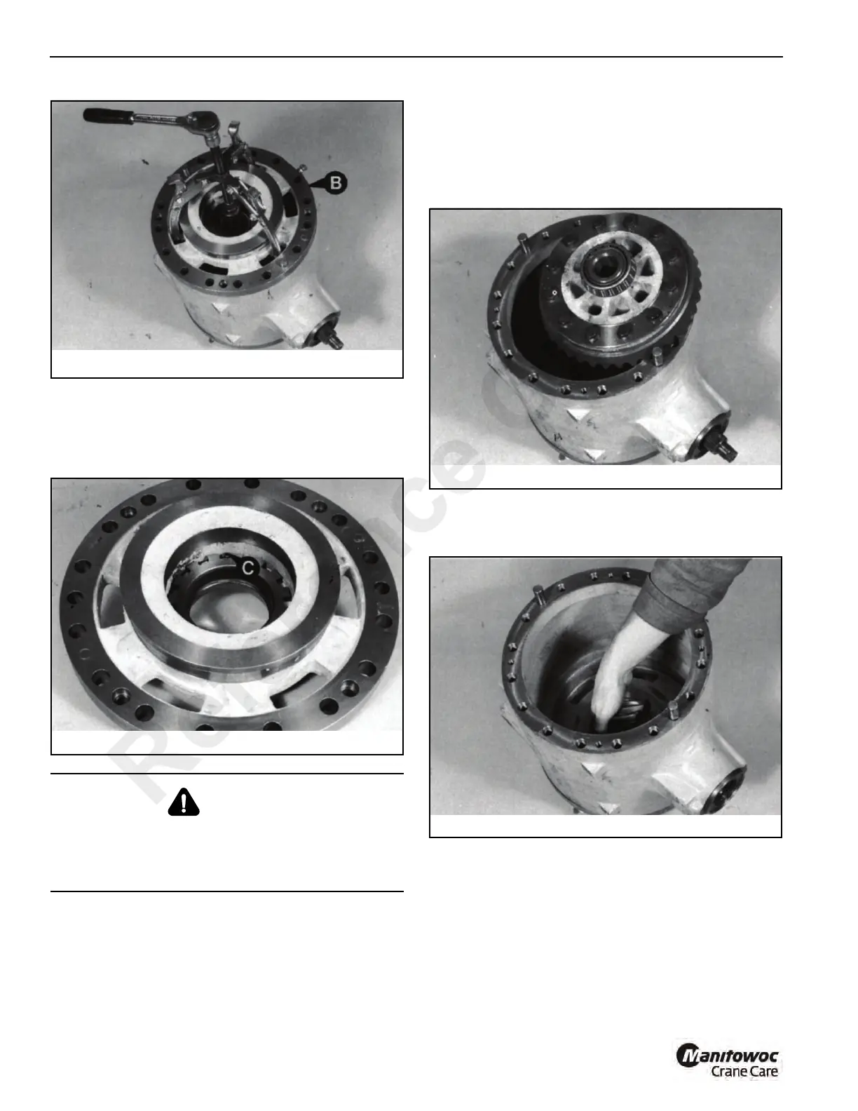
7. Drive out the differential side nut locking pin C
Figure 8-16, to allow readjustment upon assembly.
Remove the other brake piston housing only if damaged,
but remove its locking pin C regardless (to allow side
load adjustment upon assembly).
8. Lift out the crownwheel/differential assembly
Figure 8-17.
NOTE: If both brake piston housings are removed, put a
mark on the crownwheel end of the drive head
casing to ensure that the assembly is returned to its
original position.
9. Using a soft hammer, hit the pinion end shaft until the
piston is free from its front bearing. Remove the pinion
Figure 8-18.
CAUTION
METAL SPLINTERS. You can be injured by flying metal
splinter when driving metal pins in and out. Use a soft
faced hammer or drift to remove and install metal pins.
Always wear safety glasses.
Reference Only
 Loading...


