GROVE Published 10-21-2010, Control# 198-04 8-13
5540F/YB5515 SERVICE MANUAL AXLES/DRIVE SHAFTS/WHEELS AND TIRES
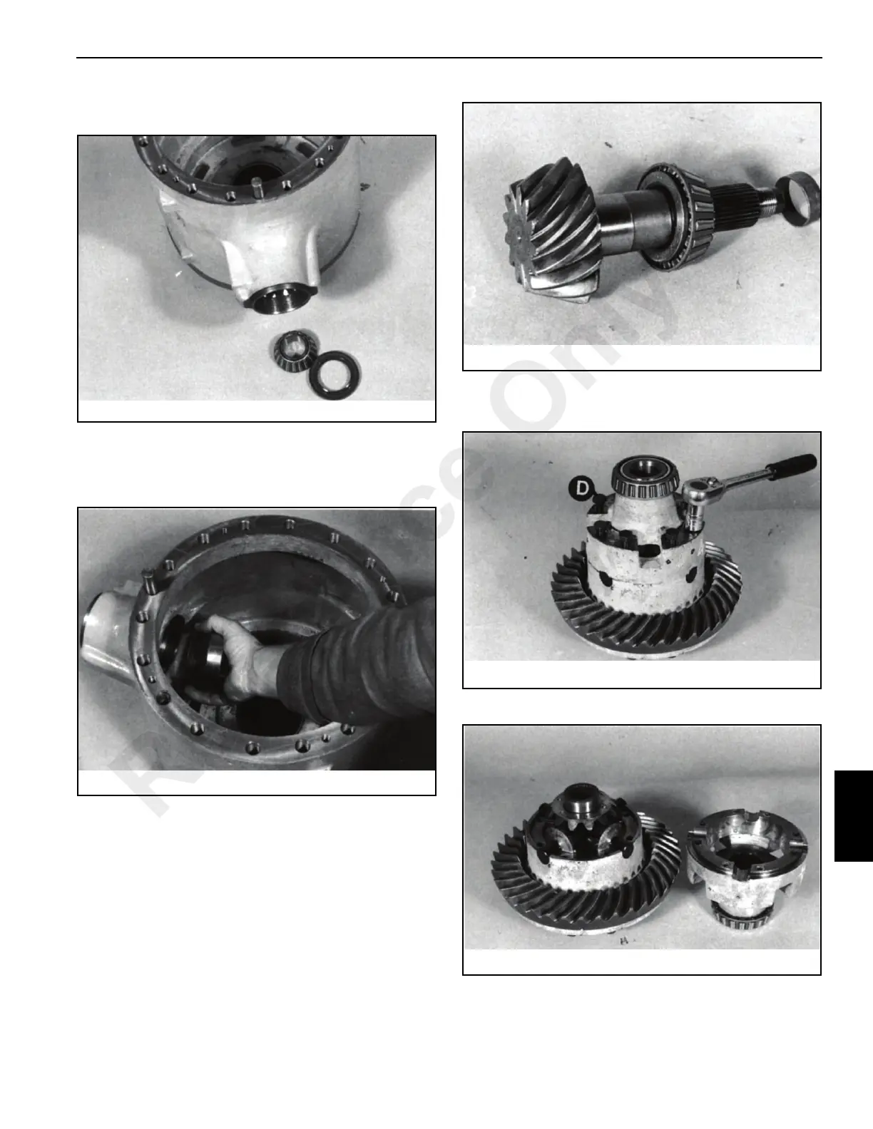
10. Remove the pinion seal and outer bearing cone
Figure 8-19.
11. If necessary, drive out the pinion inner bearing cup and
shims Figure 8-20. Discard the shims. Repeat for the
outer bearing cup, if required. There are no shims for the
outer bearing cup.
12. Remove and discard the pinion collapsible spacer
Figure 8-21. Pull of the bearing cone.
13. To dismantle the differential assembly:
a. Remove bolts D Figure 8-22.
b. Lift off the top half housing Figure 8-23.
Reference Only
 Loading...


