11-19
5540F/YB5515 SERVICE MANUAL STRUCTURALS
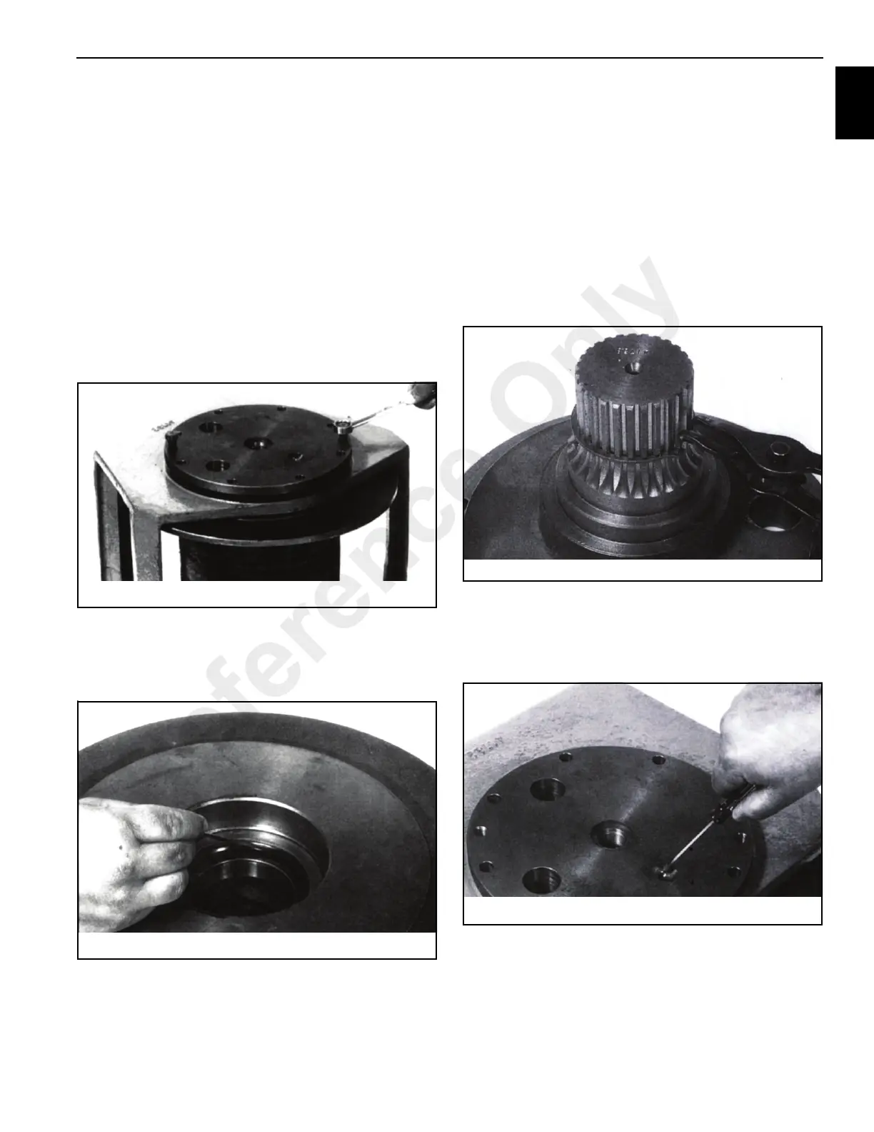
approximately the middle of one of planet gear
teeth.
b. Using a screwdriver or your finger, rotate the planet
gear back and forth, reading the movement on the
dial indicator. If the total movement is greater than
0.025 inches (0.64 mm), then the drum should be
replaced.Using the same procedure as in Step 5,
remove the output planet set from the drum. Inspect
the planet set for wear and repair as necessary. See
Planet Sets (Page 6-26) for repair instructions.
8. Turn the winch over onto the motor end and remove the
capscrews holding the output shaft (3, Figure 11-24) into
the mounting bracket. Install two of the capscrews into
the extra threaded holes in the output shaft
(Figure 11-23) and evenly tighten them until the output
shaft is free from the mounting bracket.
9. Remove the drum from the mounting bracket.
10. Remove the bearing and seal (Figure 11-25) from the
drum and inspect the bearing for signs of pitting and
spalling.
Assembly
1. Thoroughly clean all parts. Replace those which show
wear.
2. After inspecting the drum for excessive wear in the gear
teeth and both the drum and mounting bracket for
structural integrity, install bearing (5, Figure 11-25) and
seal 6 into the drum. Stand the mounting bracket up on
the motor end and slide the drum into it. Make sure the
drum is installed in the same direction as it was removed
or the winch assembly will be wrong when completed.
3. Check the snap ring (Figure 11-26) to ensure it is in its
groove and not bend over. Replace if necessary.
4. Install the output shaft (Figure 11-27) into the bracket
and drum, making sure to align the shaft with the bearing
in the drum. Make sure the alignment of the fill and drain
holes is correct. Tighten the capscrews to a 100 to110
lb-ft. (130 to 143 Nm).
5. Turn the assembly over onto the output shaft side and
install the output planet carrier. Use the same eyebolts
and chain used to disassemble the unit.
6. Put a light coating of grease on the thrust washer (8,
Figure 11-20) to keep it in place.Install it into the output
Reference Only
 Loading...


