11-25
5540F/YB5515 SERVICE MANUAL STRUCTURALS
4. Inspect each new seal (8, Figure 11-33) to make sure it
has an o-ring (Figure 11-46) in the groove.
5. Install one seal into the bore of the break housing with
the o-ring facing out. Install the other seal with o-ring
facing in.
6. Install the piston into the brake housing and gently tap it
down until it is seated.
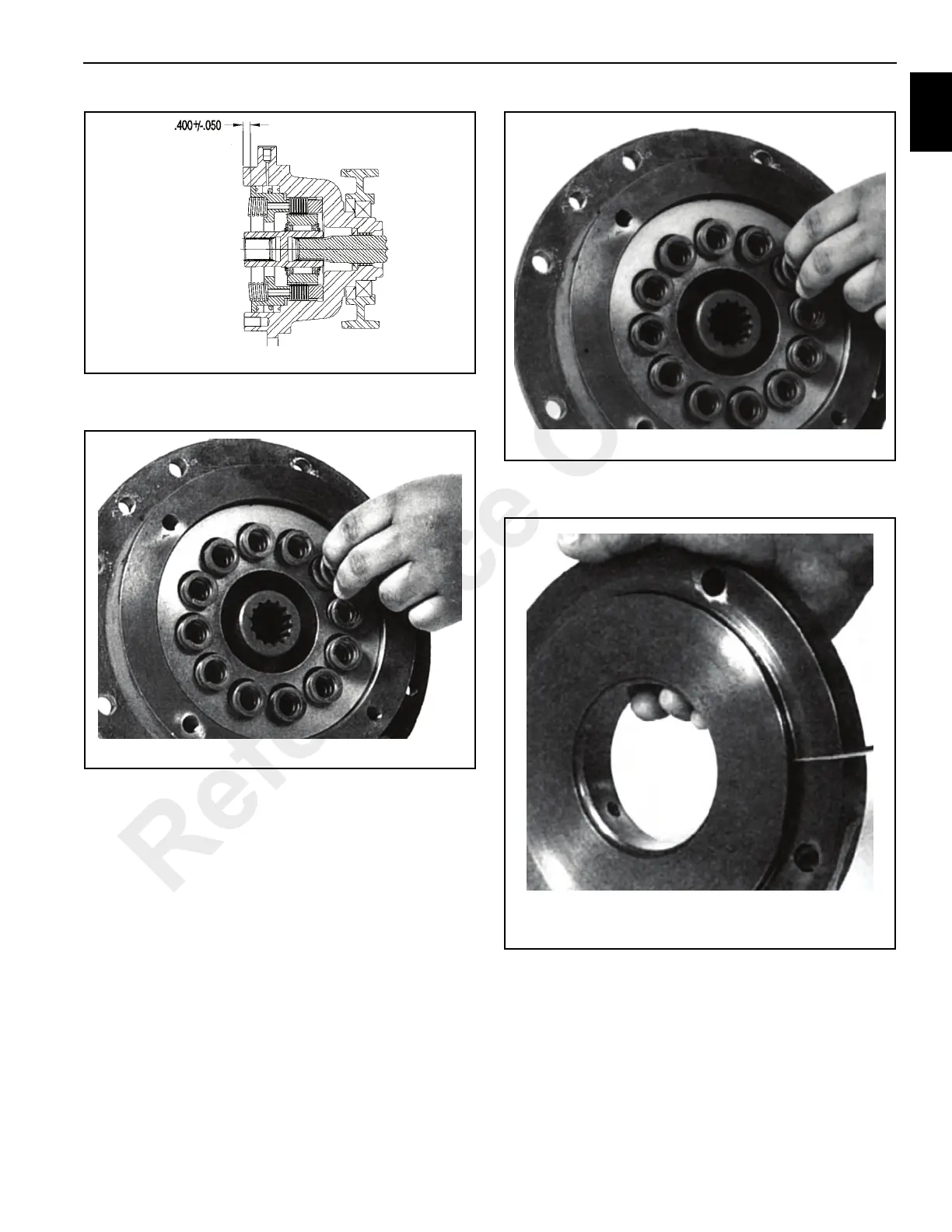
7. Install the springs (Figure 11-47) into the spring pockets.
If working in a horizontal position, coat the bottom of
each spring with grease to keep them in place.
8. Coat a new o-ring (Figure 11-48) with light oil and install
the o-ring into the groove on the brake cover.
9. Install the cover onto the brake housing and draw it
down evenly, alternating between opposite capscrews.
Make sure that the cover is properly aligned with brake
housing to orient the motor as it should be.
10. Check the brake release with a portable pump. Full
release should be obtained at 350 psi (1034 kPa), plus
or minus 20 psi (138 kPa). Also, check the brake for
proper operation by applying 280 psi (1929 kPa) to the
Reference Only
 Loading...


