11-35
5540F/YB5515 SERVICE MANUAL STRUCTURALS
3. Begin disassembly by removing the oil level plug and
standing the winch on the bearing support end. Tag and
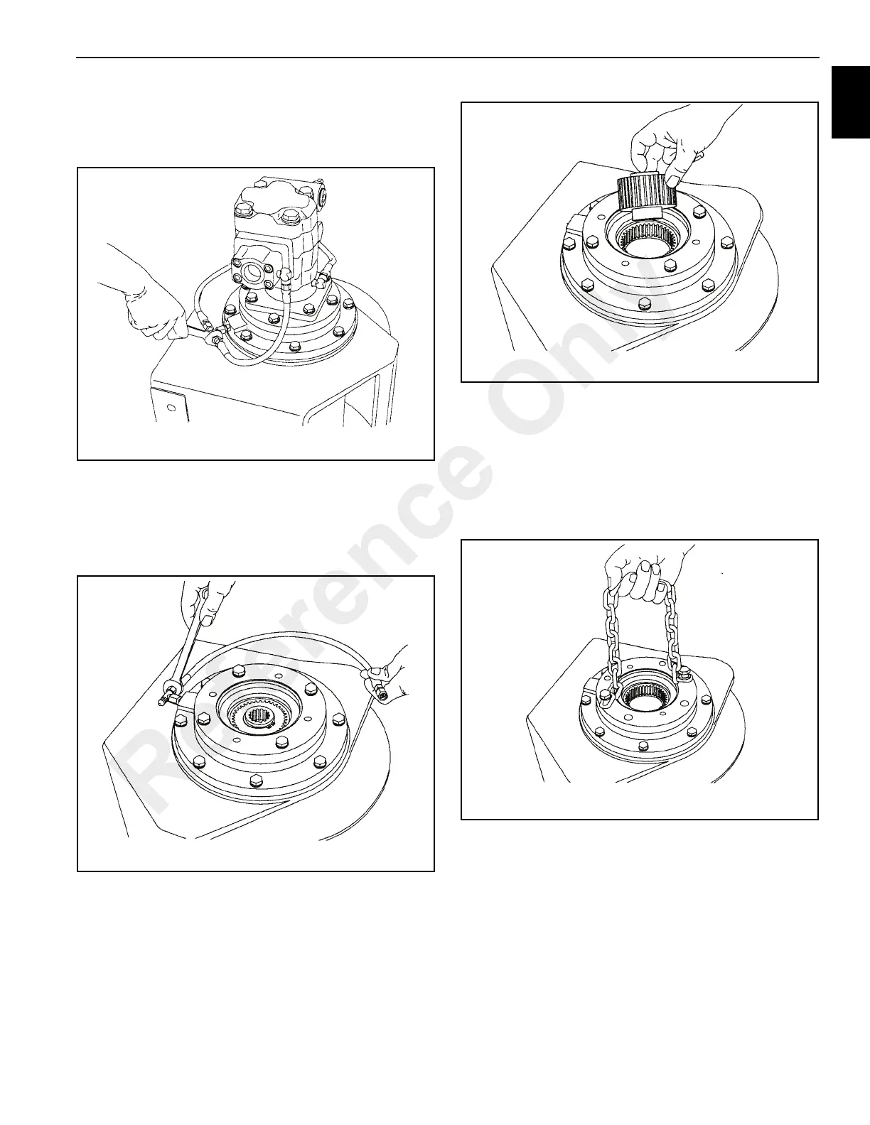
remove the hydraulic hoses that connect the brake valve
and manifold to the brake cylinder (Figure 11-63).
4. Remove the capscrews securing the motor, and lift the
motor off the winch. Remove and discard the o-ring
installed on the pilot of the motor.
5. Tag and remove the hoses and fittings from the brake
cylinder release port (Figure 11-64).
6. Remove the brake clutch (Figure 11-65) assembly from
the motor support. Refer to “Brake Clutch Service,” for
additional information.
7. Remove the motor support capscrews and install two (2)
capscrews and a short piece of chain (Figure 11-66) into
the motor mounting bolt holes. Using the chain as a
handle, lift the motor support out of the brake cylinder
being careful to avoid damaging the sealing surfaces.
Remove and discard the O ring and backup ring from the
motor support. Refer to “Motor Support-Brake Cylinder
Service” for additional information.
8. Remove the brake cylinder capscrews and install two (2)
capscrews and a short piece of chain into the motor
support mounting bolt holes. Using the chain as a
handle, lift the brake cylinder out of the drum and base,
being careful to avoid damaging the sealing or bearing
surfaces. Refer to “Motor Support-Brake Cylinder
Service” for additional information.
9. Using two heel type pry bars (Figure 11-67) placed
between the primary planet carrier and the drum
closure, pry upward to remove the drum closure.
Reference Only
 Loading...


