STRUCTURALS 5540F/YB5515 SERVICE MANUAL
11-44
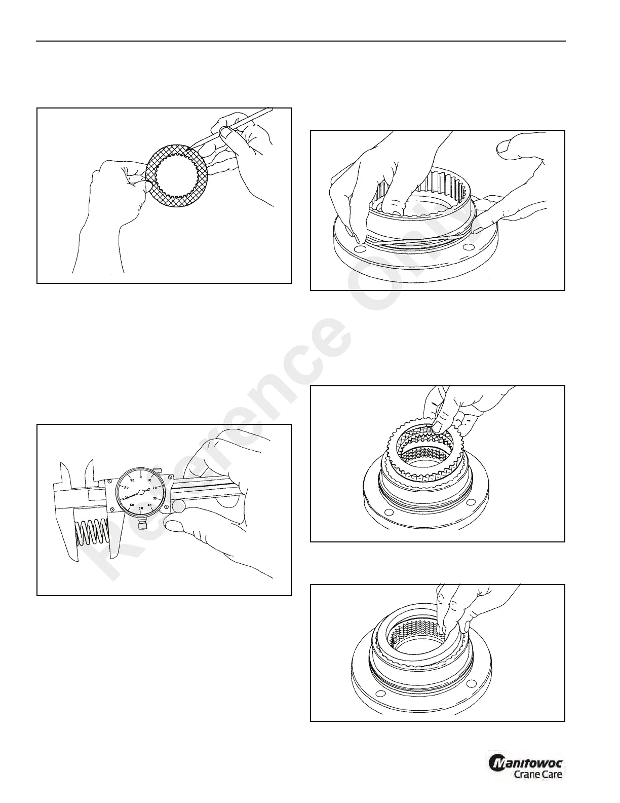
pattern visible. Replace the friction disc if the splines are
worn to a point, disc is distorted, friction material is worn
unevenly, or the groove pattern is worn away.
4. Place the steel brake disc on a flat surface and check for
distortion with a straight edge.Check surface for signs of
material transfer or hear. Replace the steel disc if the
splines are worn to a point, disc is distorted, or if it is heat
discolored.
5. Check the brake spring free length (Figure 11-100).
Minimum free length is 1-3/16 inch (30.2 mm). Check
springs for any sign of cracking or failure. If a brake
spring must be replaced, then all brake springs must be
replaced.
NOTE: Failure to replace brake springs as a set may result
in uneven brake application pressure and repeated
brake spring failure.
Assembly
1. Begin assembly by placing the motor support on the
workbench with motor mounting surface down. Install
new o-ring and brake-spring (Figure 11-101).
2. Insert first, a steel brake disc followed by a friction disc.
Then, alternate steel friction discs until seven (7) friction
and eight (8) steel discs have been installed
(Figure 11-102). Finish with a steel brake disc on top.
NOTE: It is good practice to pre-lubricate the discs in a
light motor oil prior to assembly.
3. Install the brake spacer on top of the last steel brake disc
(Figure 11-103).
Reference Only
 Loading...


