11-45
5540F/YB5515 SERVICE MANUAL STRUCTURALS
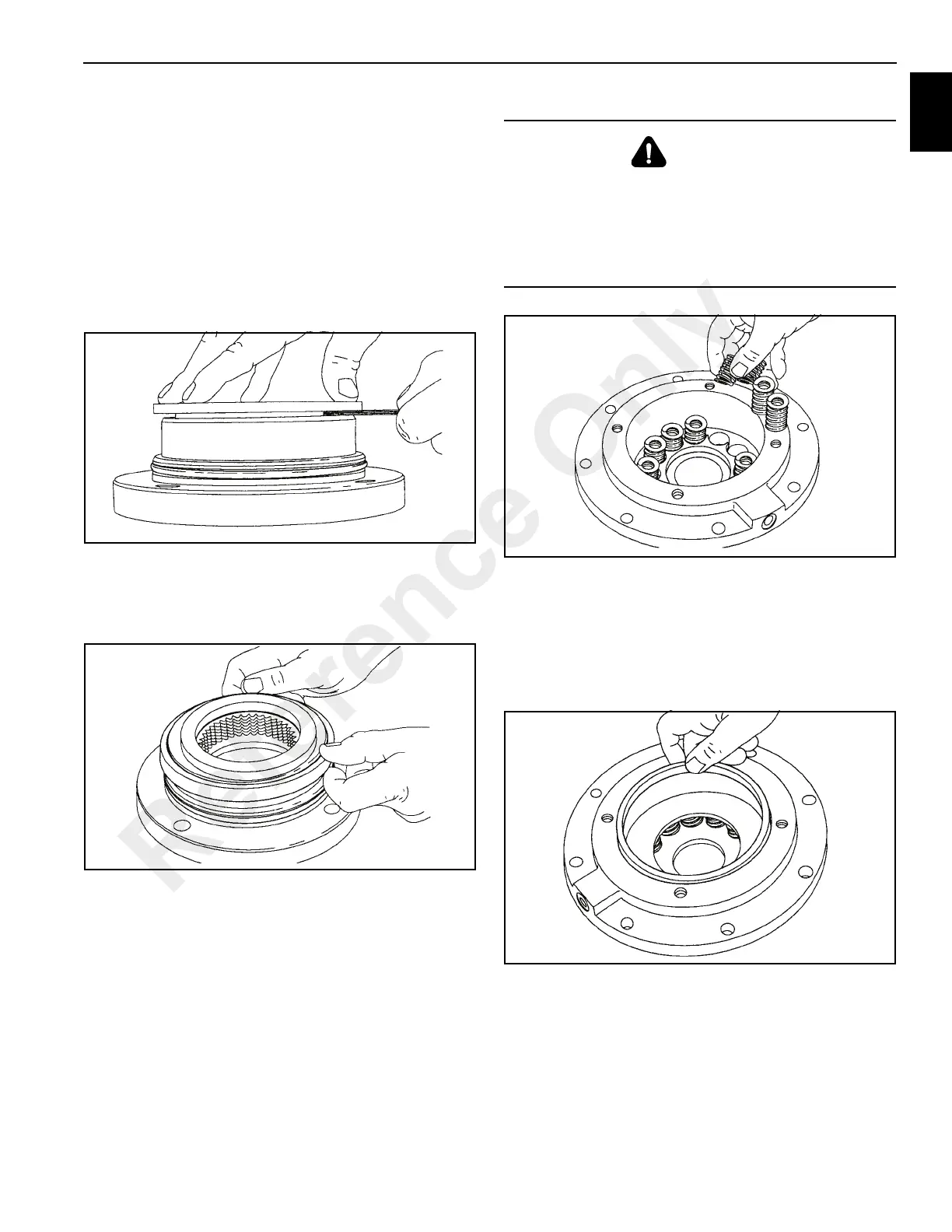
4. To check brake stack height, place a pressure plate on
top of brake spacer. Hold pressure plate down firmly by
hand and measure the clearance in three places
between the motor support and the pressure plate
(Figure 11-104). Average gap must measure between
0.153 in. (4 mm) maximum and 0.80 in. (2 mm)
minimum. If the gap exceeds the maximum limit, there
are too many brake discs in the stack-up, or the brake
discs are distorted. If the gap is less than the minimum,
there are too few discs in the stack-up, or the discs are
worn out. If the stack-up height is correct, remove
pressure plate and continue with assembly.
5. Lubricate the brake piston seal and motor support
sealing surface with petroleum jelly or hydraulic oil.
Insert a new piston seal to the motor support with the lip
seal down (Figure 11-105).
6. Install the spring spacer and then the brake springs
(Figure 11-106).
7. Install the pressure plate into the brake cylinder followed
by the piston backup ring (Figure 11-107). The close
fitting piston backup ring may be depressed slightly to
one side to lodge the backup ring in the brake cylinder
bore.Temporarily hold the pressure plate and springs in
place while lowering the brake cylinder over the motor
support.
8. Apply petroleum jelly to the entire sealing surface of the
brake cylinder and to the piston seal. Install the brake
cylinder over the motor support (Figure 11-108) being
careful to avoid damaging the piston seal or motor
support o-ring. A press may be necessary to avoid
cocking the brake cylinder during installation.
WARNING
Always use the molded spring spacer with the brake
cylinder. The brake springs must be properly positioned
by the spring spacer. Failure to install the spring spacer
may allow the springs to contact each other and become
damaged. This could result in loss of load control,
property damage, injury or death.
Reference Only
 Loading...


