• DOK-DIAX02-DDS02.1*ANA-ANW1-EN-E1,44 • 12.96
115
11. Appendix
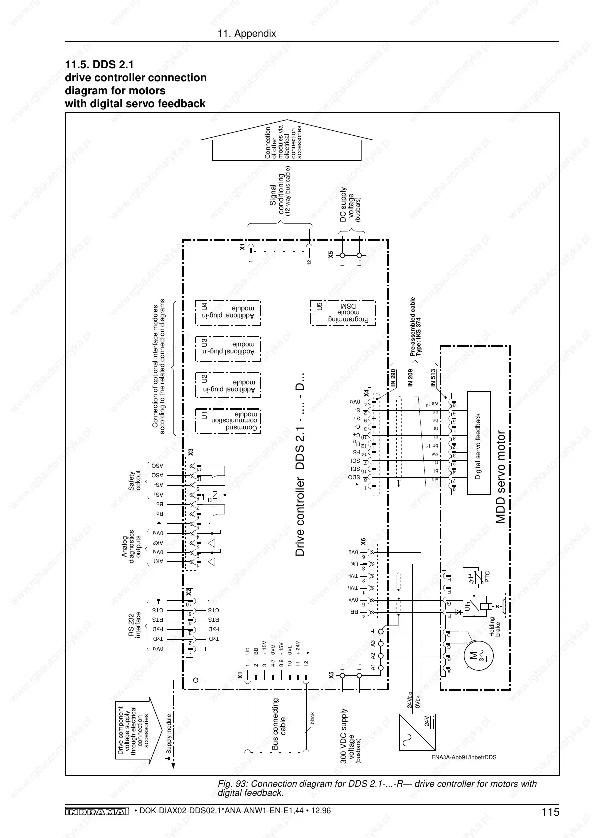
11.5. DDS 2.1
drive controller connection
diagram for motors
with digital servo feedback
Fig. 93: Connection diagram for DDS 2.1-...-R— drive controller for motors with
digital feedback.
ENA3A-Abb91/InbetrDDS
1
2
4
5
Drive controller DDS 2.1 - .... - D...
E
H
Signal
conditioning
(12-way bus cable)
X1
1
12
Connection
of other
modules via
electrical
connection
accessories
Drive component
voltage supply
through electrical
connection
accessories
MDD servo motor
M
3
A1 A3A2
A
B
C
D
X6
Holding
brake
F
G
Supply module
L -
L +
X5
300 VDC supply
voltage
(busbars)
L -
L +
DC supply
voltage
(busbars)
X5
1
8
15
7
14
SDO
SDI
SCL
FS
Digital servo feedback
X4
10
C+
3
C-
9
S+
2
S-
4
0V
M
12
U
G
3
6
1
2
3
4
5
6
7
8
9
10
11
1
2
3
4
5
10
0V
M
TxDTxD
RxDRxD
RTSRTS
AK1
0V
M
AK2
0V
M
Bb
Bb
AS+
AS-
ASQ
ASQ
X2
X3
U1
1
2
3
4-7
8,9
10
11
12
U
D
BB
+ 15V
0V
M
- 15V
0VL
+ 24V
Bus connecting
cable
black
X1
TM+
TM-
BR
0V
B
U
B
0V
B
24V
Ext
0V
Ext
24V
CTSCTS
RS 232
interface
Command
communication
module
U2
Additional plug-in
module
U3 U4
Programming
module
DSM
U5
Analog
diagnostics
outputs
Safety
lockout
9
7
4
2
3
12
8
1
5
6
10
Connection of optional interface modules
according to the related connection diagrams
PTC
U
IN 209
IN 513
IN 290
Pre-assembled cable
Type: IKS 374
vio
bl
rt
sw
bn 1
2
gr
rs
bn
gn
ws 1
2
Additional plug-in
module
Additional plug-in
module