• DOK-DIAX02-DDS02.1*ANA-ANW1-EN-E1,44 • 12.96
85
7. Commissioning the functions of the digital AC servo drive
With conventional analog servo drives operating in a velocity loop, the
axis may drift when a command value of 0V (to stop the servo axis) is
applied on account of temperature drifts of the components in the velocity
controller or due to incorrect zero-speed balancing.
The DDS 2.1 with ANALOG interface as a command communication
module allows drift-free positioning of the axis in the "velocity loop" mode
after the axis has been stopped.
This function can be called up with the signal "AH" (drive halt) on the
ANALOG interface by applying 0 V DC or by leaving the input open.
When the "drive halt" function is activated at the ANALOG interface, the
drive will come to a halt under consideration of any set torque limit (see
Section 7.11).
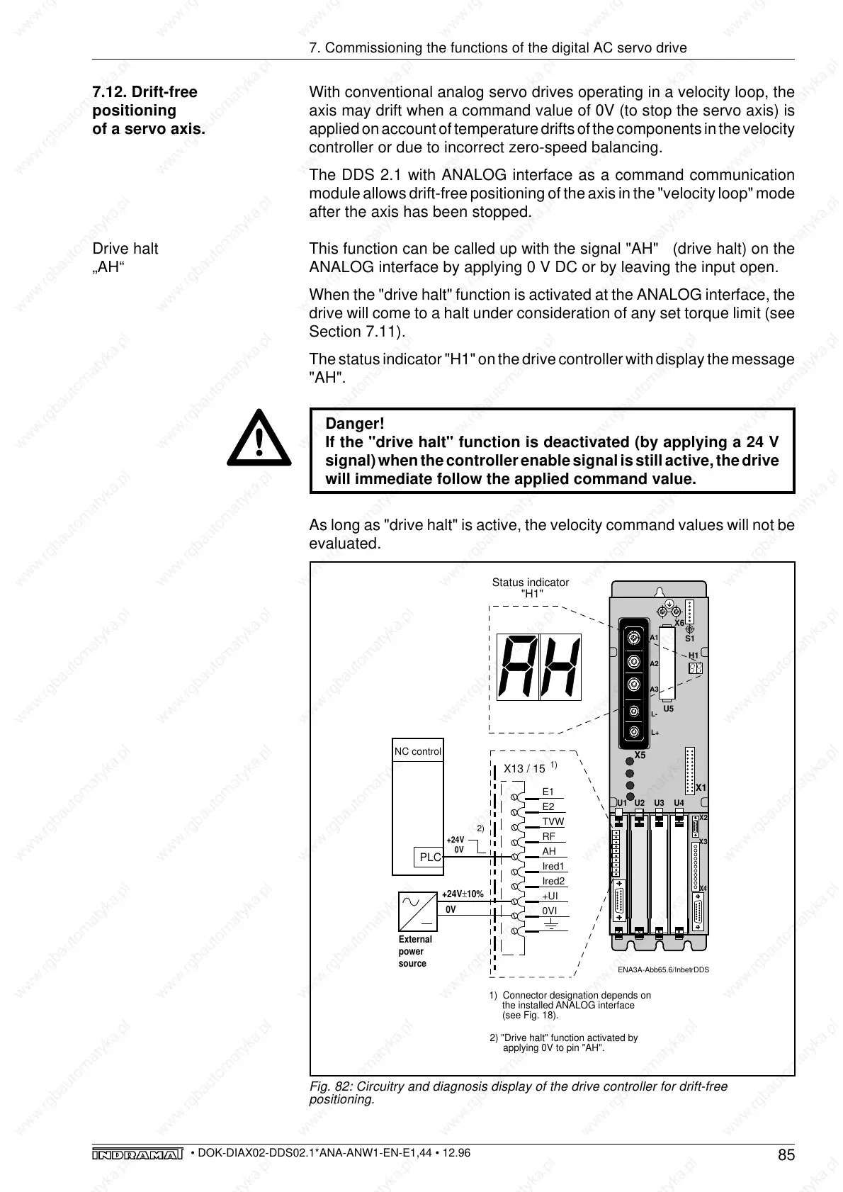
The status indicator "H1" on the drive controller with display the message
"AH".
Danger!
If the "drive halt" function is deactivated (by applying a 24 V
signal) when the controller enable signal is still active, the drive
will immediate follow the applied command value.
As long as "drive halt" is active, the velocity command values will not be
evaluated.
7.12. Drift-free
positioning
of a servo axis.
Fig. 82: Circuitry and diagnosis display of the drive controller for drift-free
positioning.
ENA3A-Abb65.6/InbetrDDS
E1
E2
TVW
RF
AH
Ired1
Ired2
+UI
0VI
X13 / 15
+24V±10%
External
power
source
0V
1)
1) Connector designation depends on
the installed ANALOG interface
(see Fig. 18).
NC control
+24V
0V
PLC
2)
2) "Drive halt" function activated by
applying 0V to pin "AH".
L-
L+
S1
A3
A1
A2
X4
X3
X6
X5
U5
U1
U3
U2
U4
H1
X1
X2
Status indicator
"H1"
Drive halt
„AH“