• DOK-DIAX02-DDS02.1*ANA-ANW1-EN-E1,44 • 12.96
95
9. Diagnostics and fault clearance
Errors detected by the drive as well as warnings and operating status
messages are displayed by the two-digit, seven-segment "Status indica-
tor H1" (see Fig. 15).
If errors are detected during the initialization phase of the microprocessor
in the drive controller, the 7-segment display of the DDS 2.1 with
ANALOG interface will indicate the most recent error. The user program
will output a list of all initializing errors which have occurred. Initializing
errors carry the error codes: 83, 84, 87, 88, 89, 91 (see Section 9.3).
Warnings issued by the controller and command errors are indicated by
a flashing display. The operating status and the error messages can be
called up at the same time via the diagnostics text in the "drive status"
message line of the operator interface for the "Drive Status" menu of the
DDS 2.1 (see Section 5.1, Fig. 36).
The different types of operating status of the drive are indicated by a two-
letter code.
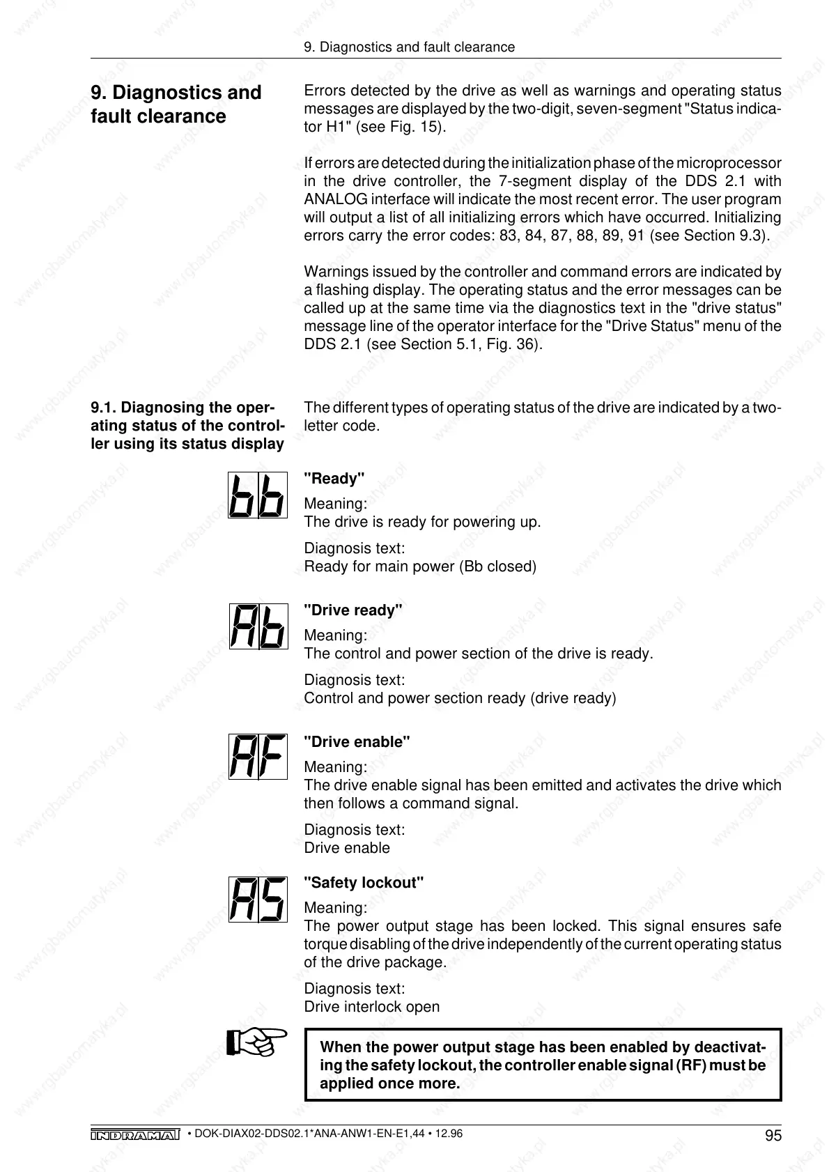
"Ready"
Meaning:
The drive is ready for powering up.
Diagnosis text:
Ready for main power (Bb closed)
"Drive ready"
Meaning:
The control and power section of the drive is ready.
Diagnosis text:
Control and power section ready (drive ready)
"Drive enable"
Meaning:
The drive enable signal has been emitted and activates the drive which
then follows a command signal.
Diagnosis text:
Drive enable
"Safety lockout"
Meaning:
The power output stage has been locked. This signal ensures safe
torque disabling of the drive independently of the current operating status
of the drive package.
Diagnosis text:
Drive interlock open
When the power output stage has been enabled by deactivat-
ing the safety lockout, the controller enable signal (RF) must be
applied once more.
9. Diagnostics and
fault clearance
9.1. Diagnosing the oper-
ating status of the control-
ler using its status display