• DOK-DIAX02-DDS02.1*ANA-ANW1-EN-E1,44 • 12.96
90
8. Final commissioning work
8. Final
commissioning
work
8.1. Preparations for
running the axis with an
NC control system
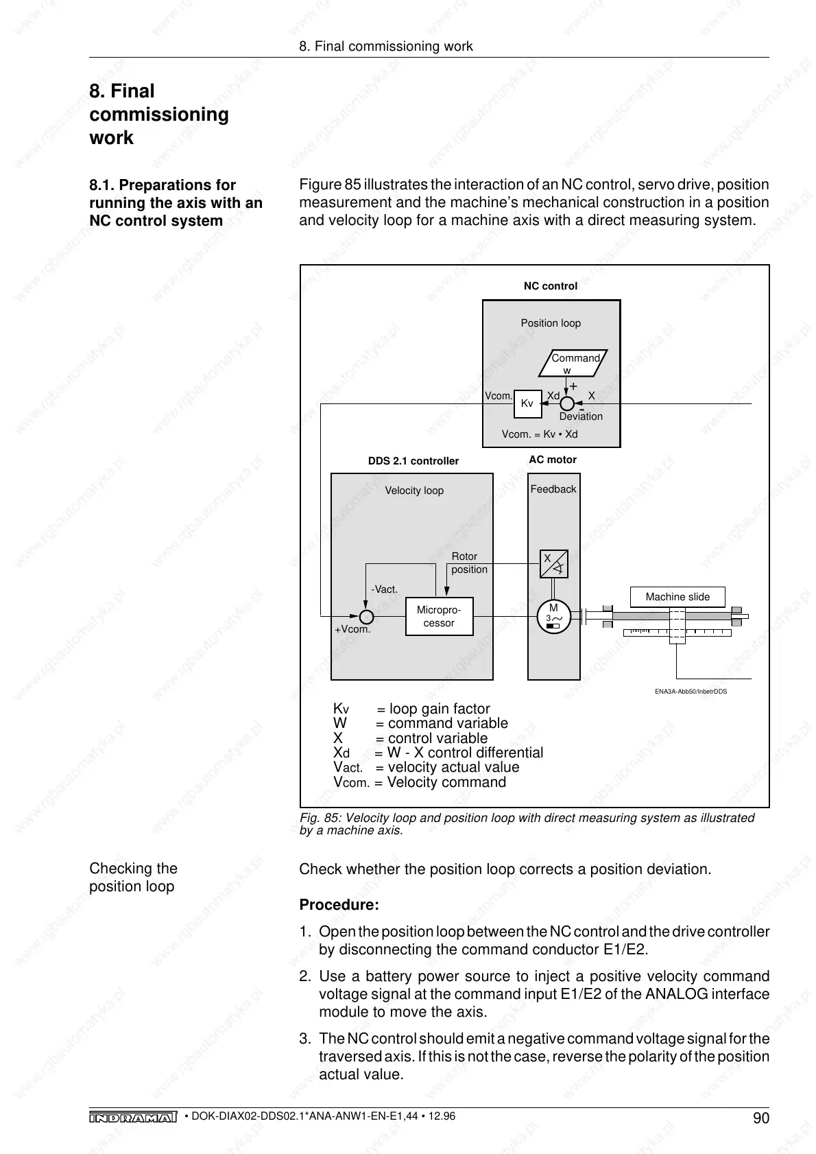
Figure 85 illustrates the interaction of an NC control, servo drive, position
measurement and the machine’s mechanical construction in a position
and velocity loop for a machine axis with a direct measuring system.
Fig. 85: Velocity loop and position loop with direct measuring system as illustrated
by a machine axis.
Position loop
NC control
Command
w
Vcom.
Vcom. = Kv • Xd
Deviation
Machine slide
AC motor
Feedback
Velocity loop
-Vact.
+Vcom.
Micropro-
cessor
Kv
-
M
3
Xd X
+
ENA3A-Abb50/InbetrDDS
X
Rotor
position
DDS 2.1 controller
K
v
= loop gain factor
W = command variable
X = control variable
X
d
= W - X control differential
V
act.
= velocity actual value
V
com.
= Velocity command
Checking the
position loop
Check whether the position loop corrects a position deviation.
Procedure:
1. Open the position loop between the NC control and the drive controller
by disconnecting the command conductor E1/E2.
2. Use a battery power source to inject a positive velocity command
voltage signal at the command input E1/E2 of the ANALOG interface
module to move the axis.
3. The NC control should emit a negative command voltage signal for the
traversed axis. If this is not the case, reverse the polarity of the position
actual value.