• DOK-DIAX02-DDS02.1*ANA-ANW1-EN-E1,44 • 12.96
64
When stopped, servo axes must be secured against involuntary start-up
if such a movement could cause injury to personnel or damage to
machinery. INDRAMAT provides protection of this type in the form of an
optional holding brake.
The holding brake for MDD motors is not designed as a service
brake. If applied with the motor running, it will wear out after
approx. 20,000 motor revolutions.
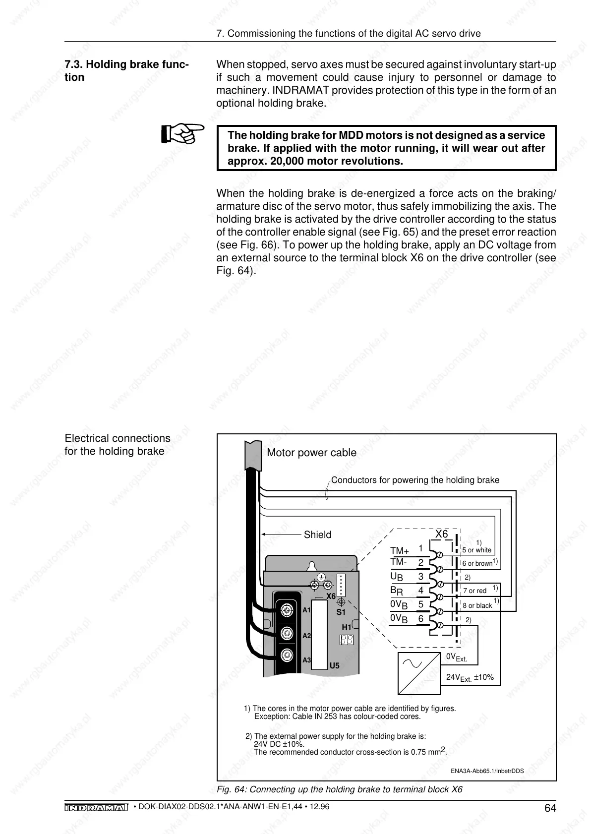
When the holding brake is de-energized a force acts on the braking/
armature disc of the servo motor, thus safely immobilizing the axis. The
holding brake is activated by the drive controller according to the status
of the controller enable signal (see Fig. 65) and the preset error reaction
(see Fig. 66). To power up the holding brake, apply an DC voltage from
an external source to the terminal block X6 on the drive controller (see
Fig. 64).
7.3. Holding brake func-
tion
7. Commissioning the functions of the digital AC servo drive
Fig. 64: Connecting up the holding brake to terminal block X6
Electrical connections
for the holding brake
S1
A3
A1
A2
X6
H1
ENA3A-Abb65.1/InbetrDDS
1
2
3
4
5
6
X6
Shield
U5
Motor power cable
±10%
0V
Ext.
24V
Ext.
5 or white
6
or brown
TM+
TM-
U
B
B
R
0V
B
0V
B
7 or red
8 or black
1)
1)
2)
2)
1)
1)
Conductors for powering the holding brake
1) The cores in the motor power cable are identified by figures.
Exception: Cable IN 253 has colour-coded cores.
2) The external power supply for the holding brake is:
24V DC ±10%.
The recommended conductor cross-section is 0.75 mm
2
.